RankRizz

Semiconductor Electronics — JEE Main Previous Year Questions

Every Semiconductor Electronics question JEE Main has set from 2004–2026, grouped by the idea it tests rather than the order of the syllabus. 253 questions across 6 distinct ideas. Free to read, answer key on every one.

Questions

253

Distinct ideas

6

Share of marks

4.4%

Difficulty

EASY

The ideas inside Semiconductor Electronics

A chapter is not one subject — it is a handful of procedures the examiner reuses. These are the ones Semiconductor Electronics questions actually test.

Every Semiconductor Electronics question

181–200 OF 253 · NEWEST FIRST

JEE MAIN 2019 · 09 JAN S2p-n junction diode and its characteristicsTRANSCRIBED

Ge and Si diodes start conducting at 0.3 V and 0.7 V respectively. In the following figure if Ge diode connection are reversed, the value of V0V_0 changes by: (assume that the Ge diode has large breakdown voltage)
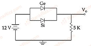
Figure for JEE Main 2019 Physics question on p-n junction diode and its characteristics
  1. A

    0.8 V

  2. B

    0.4 V

  3. C

    0.2 V

  4. D

    0.6 V

JEE MAIN 2019 · 11 JAN S2p-n junction diode and its characteristicsTRANSCRIBED

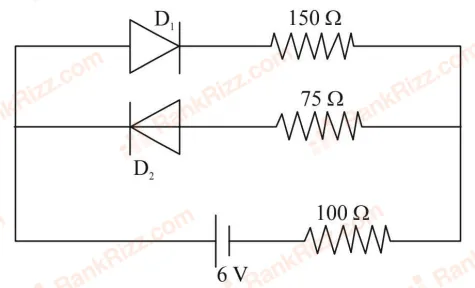
The circuit shown below contains two ideal diodes, each with a forward resistance of 50Ω50\Omega. If the battery voltage is 6 V, the current through the 100Ω100\Omega resistance (in Amperes) is:

Figure for JEE Main 2019 Physics question on p-n junction diode and its characteristics
  1. A

    0.036

  2. B

    0.02

  3. C

    0.027

  4. D

    0.03

JEE MAIN 2019 · 10 JAN S1Logic gates and digital circuitsTRANSCRIBED

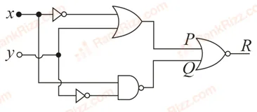
To get output '1' at R, for the given logic gate circuit the input values must be:

Figure for JEE Main 2019 Physics question on Logic gates and digital circuits
  1. A

    X=1,Y=1X = 1, Y = 1

  2. B

    X=0,Y=0X = 0, Y = 0

  3. C

    X=0,Y=1X = 0, Y = 1

  4. D

    X=1,Y=0X = 1, Y = 0

JEE MAIN 2019 · 12 JAN S2Transistors (older syllabus)TRANSCRIBED

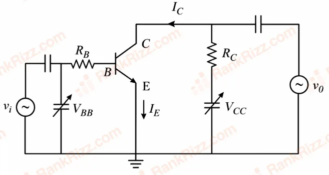
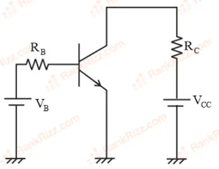
In the figure, given that VBBV_{BB} supply can vary from 0 to 5.0 V, VCC=5V_{CC} = 5 V, βdc=200\beta_{dc} = 200, RB=100R_B = 100 kΩ\Omega, RC=1R_C = 1 kΩ\Omega and VBE=1.0V_{BE} = 1.0 V. The minimum base current and the input voltage at which the transistor will go to saturation, will be, respectively:

Figure for JEE Main 2019 Physics question on Transistors (older syllabus)
  1. A

    25μA25 \mu A and 2.8 V

  2. B

    20μA20\mu A and 2.8V

  3. C

    25μA25\mu A and 3.5V

  4. D

    20μA20\mu A and 3.5V

JEE MAIN 2019 · 12 APR S2Zener diode, LED, photodiode and solar cellTRANSCRIBED

Figure shows a DC voltage regulator circuit, with a Zener diode of breakdown voltage = 6 V. If the unregulated input voltage varies between 10 V to 16 V, then what is the maximum Zener current?

Figure for JEE Main 2019 Physics question on Zener diode, LED, photodiode and solar cell
  1. A

    1.5 mA

  2. B

    3.5 mA

  3. C

    7.5 mA

  4. D

    2.5 mA

JEE MAIN 2019 · 08 APR S1Zener diode, LED, photodiode and solar cellTRANSCRIBED

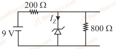
The reverse break down voltage of a Zener diode is 5.6 V in the given circuit.

Figure for JEE Main 2019 Physics question on Zener diode, LED, photodiode and solar cell

The current Iz_z through the Zener is:

  1. A

    10 mA

  2. B

    7 mA

  3. C

    17 mA

  4. D

    15 mA

JEE MAIN 2019 · 08 APR S2Transistors (older syllabus)TRANSCRIBED

A common emitter amplifier circuit, built using an NPN transistor, is shown in the figure. Its dc current gain is 250, RC=1R_C = 1 kΩ\Omega and VCC=10V_{CC} = 10 V. The minimum base current for VCEV_{CE} to reach saturation is:

Figure for JEE Main 2019 Physics question on Transistors (older syllabus)
  1. A

    10 μ\muA

  2. B

    40 μ\muA

  3. C

    7 μ\muA

  4. D

    100 μ\muA

JEE MAIN 2019 · 09 APR S1Transistors (older syllabus)TRANSCRIBED

An NPN transistor is used in common emitter configuration as an amplifier with 1 kΩ\Omega load resistance. Signal voltage of 10 mV is applied across the base-emitter. This produces a 3 mA change in the collector current and 15 μ\muA change in the base current of the amplifier. The input resistance and voltage gain are:

  1. A

    0.33 kΩ\Omega, 1.5

  2. B

    0.67 kΩ\Omega, 300

  3. C

    0.67 kΩ\Omega, 200

  4. D

    0.33 kΩ\Omega, 300

JEE MAIN 2019 · 12 APR S1Logic gates and digital circuitsTRANSCRIBED

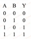
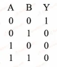
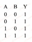
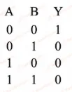
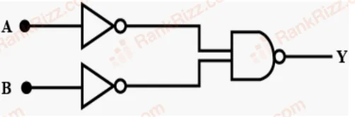
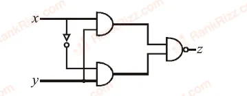
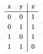
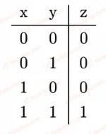
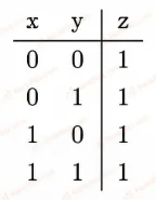
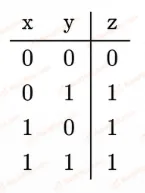
The truth table for the circuit given in the figure is:

Figure for JEE Main 2019 Physics question on Logic gates and digital circuits
  1. A
    Figure for JEE Main 2019 Physics question on Logic gates and digital circuits
  2. B
    Figure for JEE Main 2019 Physics question on Logic gates and digital circuits
  3. C
    Figure for JEE Main 2019 Physics question on Logic gates and digital circuits
  4. D
    Figure for JEE Main 2019 Physics question on Logic gates and digital circuits
JEE MAIN 2019 · 10 JAN S2Zener diode, LED, photodiode and solar cellTRANSCRIBED

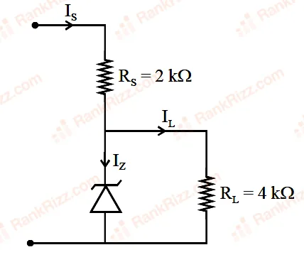
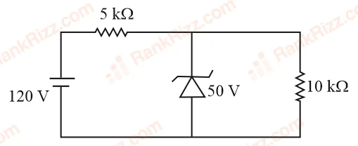
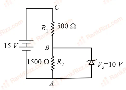
For the circuit shown below, the current through the Zener diode is:

Figure for JEE Main 2019 Physics question on Zener diode, LED, photodiode and solar cell
  1. A

    zero

  2. B

    5 mA

  3. C

    9 mA

  4. D

    14 mA

JEE MAIN 2019 · 09 APR S2Logic gates and digital circuitsTRANSCRIBED

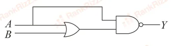
The logic gate equivalent to the given logic circuit is:

Figure for JEE Main 2019 Physics question on Logic gates and digital circuits
  1. A

    NAND

  2. B

    AND

  3. C

    NOR

  4. D

    OR

JEE MAIN 2019 · 12 APR S2Transistors (older syllabus)TRANSCRIBED

In a CE transistor amplifier, the audio signal voltage across the collector resistance of 2 kΩ is 2 V, if the base resistance is 1 kΩ and the current amplification of the transistor is 100 then the input signal voltage is

  1. A

    10 mV

  2. B

    1 mV

  3. C

    0.1 V

  4. D

    1 V

JEE MAIN 2019 · 10 APR S2Zener diode, LED, photodiode and solar cellTRANSCRIBED

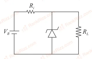
The figure represents a voltage regulator circuit using a Zener diode. The breakdown voltage of the Zener diode is 6 V and the load resistance is, RL_L = 4 kΩ. The series resistance of the circuit is Ri_i = 1 kΩ. If the battery voltage VB_B varies from 8 V to 16 V, what are the minimum and maximum values of the current through Zener diode?

Figure for JEE Main 2019 Physics question on Zener diode, LED, photodiode and solar cell
  1. A

    0.5 mA; 6 mA

  2. B

    1 mA; 8.5 mA

  3. C

    0.5 mA; 8.5 mA

  4. D

    1.5 mA; 8.5 mA

JEE MAIN 2019 · 12 APR S1Transistors (older syllabus)TRANSCRIBED

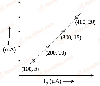
The transfer characteristic curve of a transistor, having input and output resistance 100 Ω and 100 kΩ respectively, is shown in the figure. The voltage and power gain, are respectively:

Figure for JEE Main 2019 Physics question on Transistors (older syllabus)
  1. A

    5×1045 \times 10^4, 2.5×1062.5 \times 10^6

  2. B

    2.5×1042.5 \times 10^4, 2.5×1062.5 \times 10^6

  3. C

    5×1045 \times 10^4, 5×1065 \times 10^6

  4. D

    5×1045 \times 10^4, 5×1055 \times 10^5

JEE MAIN 2018 · 15 APR S1Transistors (older syllabus)TRANSCRIBED

In a common emitter configuration with suitable bias, it is given than RLR_L is the load resistance and RBER_{BE} is small signal dynamic resistance (input side). Then, voltage gain, current gain and power gain are given, respectively, by: [β\beta is current gain, IBI_B, ICI_C, IEI_E are respectively base, collector and emitter currents]

  1. A

    βRLRBE,ΔIEΔIB,β2RLRBE\beta \frac{R_L}{R_{BE}}, \frac{\Delta I_E}{\Delta I_B}, \beta^2 \frac{R_L}{R_{BE}}

  2. B

    β2RLRBE,ΔICΔIB,βRLRBE\beta^2 \frac{R_L}{R_{BE}}, \frac{\Delta I_C}{\Delta I_B}, \beta \frac{R_L}{R_{BE}}

  3. C

    β2RLRBE,ΔICΔIE,β2RLRBE\beta^2 \frac{R_L}{R_{BE}}, \frac{\Delta I_C}{\Delta I_E}, \beta^2 \frac{R_L}{R_{BE}}

  4. D

    βRLRBE,ΔICΔIB,β2RLRBE\beta \frac{R_L}{R_{BE}}, \frac{\Delta I_C}{\Delta I_B}, \beta^2 \frac{R_L}{R_{BE}}

JEE MAIN 2018 · 08 APR OFFLINETransistors (older syllabus)TRANSCRIBED

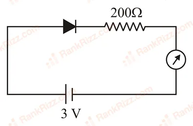
The reading of the ammeter for a silicon diode in the given circuit is:
Figure for JEE Main 2018 Physics question on Transistors (older syllabus)

  1. A

    13.5 mA

  2. B

    0

  3. C

    15 mA

  4. D

    11.5 mA

JEE MAIN 2018 · 15 APR S2Logic gates and digital circuitsTRANSCRIBED

Truth table for the given circuit will be:

Figure for JEE Main 2018 Physics question on Logic gates and digital circuits
  1. A
    Figure for JEE Main 2018 Physics question on Logic gates and digital circuits
  2. B
    Figure for JEE Main 2018 Physics question on Logic gates and digital circuits
  3. C
    Figure for JEE Main 2018 Physics question on Logic gates and digital circuits
  4. D
    Figure for JEE Main 2018 Physics question on Logic gates and digital circuits
JEE MAIN 2018 · 16 APR ONLINEZener diode, LED, photodiode and solar cellTRANSCRIBED

In the given circuit the current through zener diode is:

Figure for JEE Main 2018 Physics question on Zener diode, LED, photodiode and solar cell
  1. A

    3.3 mA

  2. B

    2.5 mA

  3. C

    5.5 mA

  4. D

    6.7 mA

JEE MAIN 2017 · 08 APR ONLINEp-n junction diode and its characteristicsTRANSCRIBED

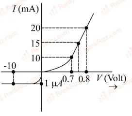
The V−IV - I characteristic of a diode is shown in the figure. The ratio of forward to reverse bias resistance is:

Figure for JEE Main 2017 Physics question on p-n junction diode and its characteristics
  1. A

    100

  2. B

    10610^6

  3. C

    10−610^{-6}

  4. D

    10

JEE MAIN 2017 · 02 APR OFFLINETransistors (older syllabus)TRANSCRIBED

In a common emitter amplifier circuit using an nn-pp-nn transistor, the phase difference between the input and the output voltages will be:

  1. A

    180°

  2. B

    45°

  3. C

    90°

  4. D

    135°