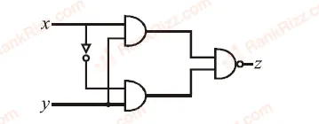
Truth table for the given circuit will be:
Upper branch input to upper AND gate=x\text{Upper branch input to upper AND gate} = xUpper branch input to upper AND gate=x
Lower branch input to upper AND gate=xˉ\text{Lower branch input to upper AND gate} = \bar{x}Lower branch input to upper AND gate=xˉ
Output of upper AND gate=x⋅xˉ=0\text{Output of upper AND gate} = x \cdot \bar{x} = 0Output of upper AND gate=x⋅xˉ=0
Upper branch input to lower AND gate=y\text{Upper branch input to lower AND gate} = yUpper branch input to lower AND gate=y
Lower branch input to lower AND gate=y\text{Lower branch input to lower AND gate} = yLower branch input to lower AND gate=y
Output of lower AND gate=y⋅y=y\text{Output of lower AND gate} = y \cdot y = yOutput of lower AND gate=y⋅y=y
z=0⋅y‾=0‾=1z = \overline{0 \cdot y} = \overline{0} = 1z=0⋅y=0=1
Tagged Logic gates and digital circuits. Machine-assigned, so read it as a strong shortlist rather than a verdict.