To get output '1' at R, for the given logic gate circuit the input values must be:
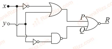
X=1,Y=1X = 1, Y = 1X=1,Y=1
X=0,Y=0X = 0, Y = 0X=0,Y=0
X=0,Y=1X = 0, Y = 1X=0,Y=1
X=1,Y=0X = 1, Y = 0X=1,Y=0
P=Xˉ+YP = \bar{X} + YP=Xˉ+Y
Q=X⋅Yˉ‾Q = \overline{X \cdot \bar{Y}}Q=X⋅Yˉ
R=P+Q‾R = \overline{P + Q}R=P+Q
R=1 ⟹ P+Q‾=1 ⟹ P+Q=0R = 1 \implies \overline{P + Q} = 1 \implies P + Q = 0R=1⟹P+Q=1⟹P+Q=0
⟹ P=0andQ=0\implies P = 0 \quad \text{and} \quad Q = 0⟹P=0andQ=0
Xˉ+Y=0 ⟹ Xˉ=0 and Y=0 ⟹ X=1, Y=0\bar{X} + Y = 0 \implies \bar{X} = 0 \text{ and } Y = 0 \implies X = 1, \, Y = 0Xˉ+Y=0⟹Xˉ=0 and Y=0⟹X=1,Y=0
Verifying, Q=1⋅0ˉ‾=1⋅1‾=1ˉ=0Q = \overline{1 \cdot \bar{0}} = \overline{1 \cdot 1} = \bar{1} = 0Q=1⋅0ˉ=1⋅1=1ˉ=0
Tagged Logic gates and digital circuits. Machine-assigned, so read it as a strong shortlist rather than a verdict.