RankRizz

Semiconductor Electronics — JEE Main Previous Year Questions

Every Semiconductor Electronics question JEE Main has set from 2004–2026, grouped by the idea it tests rather than the order of the syllabus. 253 questions across 6 distinct ideas. Free to read, answer key on every one.

Questions

253

Distinct ideas

6

Share of marks

4.4%

Difficulty

EASY

The ideas inside Semiconductor Electronics

A chapter is not one subject — it is a handful of procedures the examiner reuses. These are the ones Semiconductor Electronics questions actually test.

Every Semiconductor Electronics question

221–240 OF 253 · NEWEST FIRST

JEE MAIN 2014 · 11 APR ONLINEZener diode, LED, photodiode and solar cellTRANSCRIBED

A Zener diode is connected to a battery and a load as shown below:
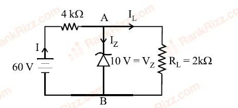
Figure for JEE Main 2014 Physics question on Zener diode, LED, photodiode and solar cell


The currents, I, IZ_Z and IL_L are respectively.

  1. A

    15 mA, 5 mA, 10 mA

  2. B

    15 mA, 7.5 mA, 7.5 mA

  3. C

    12.5 mA, 5 mA, 7.5 mA

  4. D

    12.5 mA, 7.5 mA, 5 mA
JEE MAIN 2013 · 23 APR ONLINELogic gates and digital circuitsTRANSCRIBED

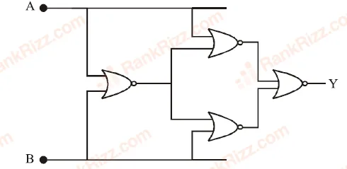
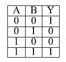
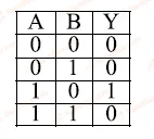
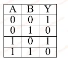
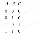
A system of four gates is set up as shown. The 'truth table' corresponding to this system is :

Figure for JEE Main 2013 Physics question on Logic gates and digital circuits
  1. A
    Figure for JEE Main 2013 Physics question on Logic gates and digital circuits
  2. B
    Figure for JEE Main 2013 Physics question on Logic gates and digital circuits
  3. C
    Figure for JEE Main 2013 Physics question on Logic gates and digital circuits
  4. D
    Figure for JEE Main 2013 Physics question on Logic gates and digital circuits
JEE MAIN 2013 · 09 APR ONLINELogic gates and digital circuitsTRANSCRIBED

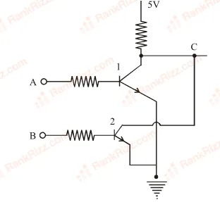
Consider two npn transistors as shown in the figure. If 0 Volts corresponds to false and 5 Volts correspond to true, then the output at C corresponds to :

Figure for JEE Main 2013 Physics question on Logic gates and digital circuits
  1. A

    A NAND B

  2. B

    A OR B

  3. C

    A AND B

  4. D

    A NOR B

JEE MAIN 2013 · 25 APR ONLINELogic gates and digital circuitsTRANSCRIBED

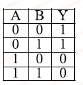
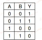
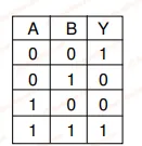
Which of the following circuits correctly represents the following truth table?

Figure for JEE Main 2013 Physics question on Logic gates and digital circuits
  1. A
    Figure for JEE Main 2013 Physics question on Logic gates and digital circuits
  2. B
    Figure for JEE Main 2013 Physics question on Logic gates and digital circuits
  3. C
    Figure for JEE Main 2013 Physics question on Logic gates and digital circuits
  4. D
    Figure for JEE Main 2013 Physics question on Logic gates and digital circuits
JEE MAIN 2013 · 07 APR ONLINEZener diode, LED, photodiode and solar cellTRANSCRIBED

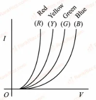
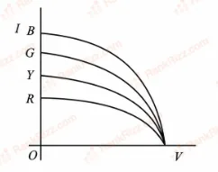
The I-V characteristics of an LED is:

  1. A
    Figure for JEE Main 2013 Physics question on Zener diode, LED, photodiode and solar cell
  2. B
    Figure for JEE Main 2013 Physics question on Zener diode, LED, photodiode and solar cell
  3. C
    Figure for JEE Main 2013 Physics question on Zener diode, LED, photodiode and solar cell
  4. D
    Figure for JEE Main 2013 Physics question on Zener diode, LED, photodiode and solar cell
JEE MAIN 2013 · 22 APR ONLINEp-n junction diode and its characteristicsTRANSCRIBED

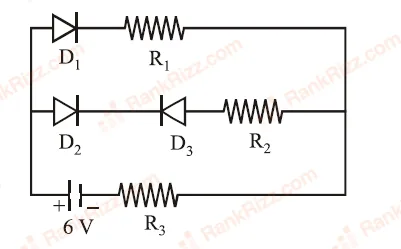
Figure shows a circuit in which three identical diodes are used. Each diode has forward resistance of 20Ω\Omega and infinite backward resistance. Resistors R1=R2=R3=50ΩR_1 = R_2 = R_3 = 50\Omega. Battery voltage is 6 V. The current through R3R_3 is :

Figure for JEE Main 2013 Physics question on p-n junction diode and its characteristics
  1. A

    50 mA

  2. B

    100 mA

  3. C

    60 mA

  4. D

    25 mA
JEE MAIN 2012Logic gates and digital circuitsTRANSCRIBED

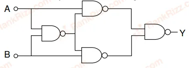
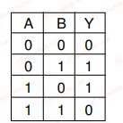
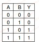
Truth table for system of four NAND gates as shown in figure isFigure for JEE Main 2012 Physics question on Logic gates and digital circuits

  1. A
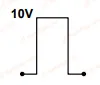
    Figure for JEE Main 2012 Physics question on Logic gates and digital circuits
  2. B
    Figure for JEE Main 2012 Physics question on Logic gates and digital circuits
  3. C
    Figure for JEE Main 2012 Physics question on Logic gates and digital circuits
  4. D
    Figure for JEE Main 2012 Physics question on Logic gates and digital circuits
JEE MAIN 2012Logic gates and digital circuitsTRANSCRIBED

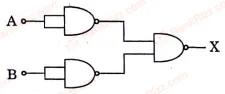
Which logic gate with inputs AA and BB performs the same operation as that performed by the following circuit?

Figure for JEE Main 2012 Physics question on Logic gates and digital circuits
  1. A

    NAND gate

  2. B

    OR gate

  3. C

    NOR gate

  4. D

    AND gate

JEE MAIN 2012Logic gates and digital circuitsTRANSCRIBED

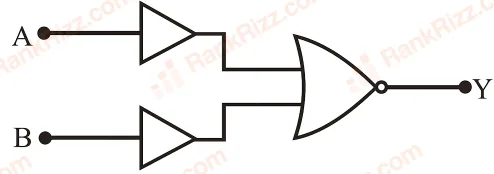
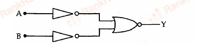
The figure shows a combination of two NOT gates and a NOR gate.

Figure for JEE Main 2012 Physics question on Logic gates and digital circuits

The combination is equivalent to a

  1. A

    NAND gate

  2. B

    NOR gate

  3. C

    AND gate

  4. D

    OR gate

JEE MAIN 2012Logic gates and digital circuitsTRANSCRIBED

Which one of the following is the Boolean expression for NOR gate?

  1. A

    Y=A+B‾Y = \overline{A+B}

  2. B

    Y=A⋅B‾Y = \overline{A\cdot B}

  3. C

    Y=A⋅BY = A\cdot B

  4. D

    Y=AˉY = \bar{A}

JEE MAIN 2012Semiconductors: energy bands, intrinsic and extrinsicTRANSCRIBED

This question has Statement 1 and Statement 2. Of the four choices given after the Statements, choose the one that best describes the two Statements. Statement 1: A pure semiconductor has negative temperature coefficient of resistance. Statement 2: On raising the temperature, more charge carriers are released into the conduction band.

  1. A

    Statement 1 is false, Statement 2 is true.

  2. B

    Statement 1 is true, Statement 2 is false.

  3. C

    Statement 1 is true, Statement 2 is true, Statement 2 is not a correct explanation of Statement 1.

  4. D

    Statement 1 is true, Statement 2 is true, Statement 2 is the correct explanation of Statement 1.

JEE MAIN 2010Logic gates and digital circuitsTRANSCRIBED

The combination of gates shown below yields
Figure for JEE Main 2010 Physics question on Logic gates and digital circuits

  1. A

    OR gate

  2. B

    NOT gate

  3. C

    XOR gate

  4. D

    NAND gate

JEE MAIN 2009Diode circuits and rectifiersTRANSCRIBED

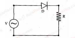
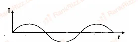
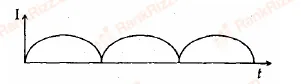
A p-n junction (D) shown in the figure can act as a rectifier. An alternating current source (V)(V) is connected in the circuit. Figure for JEE Main 2009 Physics question on Diode circuits and rectifiers

  1. A
    Figure for JEE Main 2009 Physics question on Diode circuits and rectifiers
  2. B
    Figure for JEE Main 2009 Physics question on Diode circuits and rectifiers
  3. C
    Figure for JEE Main 2009 Physics question on Diode circuits and rectifiers
  4. D
    Figure for JEE Main 2009 Physics question on Diode circuits and rectifiers
JEE MAIN 2009Logic gates and digital circuitsTRANSCRIBED

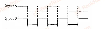
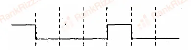
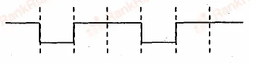
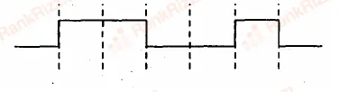
The logic circuit shown below has the input waveforms 'A' and 'B' as shown. Pick out the correct output waveform. Figure for JEE Main 2009 Physics question on Logic gates and digital circuitsFigure for JEE Main 2009 Physics question on Logic gates and digital circuits

  1. A
    Figure for JEE Main 2009 Physics question on Logic gates and digital circuits
  2. B
    Figure for JEE Main 2009 Physics question on Logic gates and digital circuits
  3. C
    Figure for JEE Main 2009 Physics question on Logic gates and digital circuits
  4. D
    Figure for JEE Main 2009 Physics question on Logic gates and digital circuits
JEE MAIN 2008Transistors (older syllabus)TRANSCRIBED

A working transistor with its three legs marked P,QP, Q and RR is tested using a multimeter. No conduction is found between PP and QQ. By connecting the common (negative) terminal of the multimeter to RR and the other (positive) terminal to PP or QQ, some resistance is seen on the multimeter. Which of the following is true for the transistor?

  1. A

    It is an npn transistor with RR as base

  2. B

    It is a pnp transistor with RR as collector

  3. C

    It is a pnp transistor with RR as emitter

  4. D

    It is an npn transistor with RR as collector

JEE MAIN 2008Logic gates and digital circuitsTRANSCRIBED

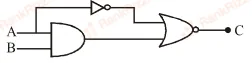
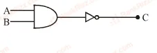
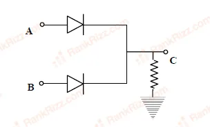
In the circuit below, AA and BB represent two inputs and CC represents the output. The circuit representsFigure for JEE Main 2008 Physics question on Logic gates and digital circuits

  1. A

    NOR gate

  2. B

    AND gate

  3. C

    NAND gate

  4. D

    OR gate

JEE MAIN 2007Diode circuits and rectifiersTRANSCRIBED

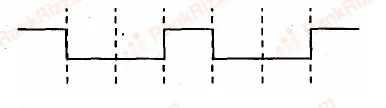
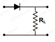
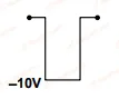
If in a p−np-n junction diode, a square input signal of 10 V is applied as shown Figure for JEE Main 2007 Physics question on Diode circuits and rectifiersFigure for JEE Main 2007 Physics question on Diode circuits and rectifiers
Then the output signal across RLR_L will be

  1. A
    Figure for JEE Main 2007 Physics question on Diode circuits and rectifiers
  2. B
    Figure for JEE Main 2007 Physics question on Diode circuits and rectifiers
  3. C
    Figure for JEE Main 2007 Physics question on Diode circuits and rectifiers
  4. D
    Figure for JEE Main 2007 Physics question on Diode circuits and rectifiers
JEE MAIN 2007Semiconductors: energy bands, intrinsic and extrinsicTRANSCRIBED

Carbon, silicon and germanium have four valence electrons each. At room temperature which one of the following statements is most appropriate?

  1. A

    The number of free conduction electrons is significant in C but small in Si and Ge.

  2. B

    The number of free conduction electrons is negligibly small in all the three.

  3. C

    The number of free electrons for conduction is significant in all the three.

  4. D

    The number of free electrons for conduction is significant only in Si and Ge but small in C.

JEE MAIN 2006Semiconductors: energy bands, intrinsic and extrinsicTRANSCRIBED

A solid which is transparent to visible light and whose conductivity increases with temperature is formed by

  1. A

    Metallic binding

  2. B

    Ionic binding

  3. C

    Covalent binding

  4. D

    Van der Waals binding

JEE MAIN 2006Semiconductors: energy bands, intrinsic and extrinsicTRANSCRIBED

If the ratio of the concentration of electrons that of holes in a semiconductor is 75\dfrac{7}{5} and the ratio of currents is 74\dfrac{7}{4}, then what is the ratio of their drift velocities?

  1. A

    47\dfrac{4}{7}

  2. B

    58\dfrac{5}{8}

  3. C

    45\dfrac{4}{5}

  4. D

    54\dfrac{5}{4}