JEE MAIN 2026Diode circuits and rectifiersTRANSCRIBED
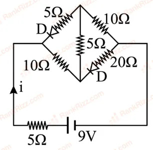
Find the value of current in the given circuit
- A
- B
- C
- D
Zero
Every Semiconductor Electronics question JEE Main has set from 2004–2026, grouped by the idea it tests rather than the order of the syllabus. 253 questions across 6 distinct ideas. Free to read, answer key on every one.
Questions
253
Distinct ideas
6
Share of marks
4.4%
Difficulty
EASY
A chapter is not one subject — it is a handful of procedures the examiner reuses. These are the ones Semiconductor Electronics questions actually test.
The share of each year’s Physics questions that came from Semiconductor Electronics, counted from the 168 papers we hold for the last 10 years, and session by session inside a year.
Steady: 4.0% of Physics questions in 2024–2026 against 4.3% in 2017–2023, and between 3.3% and 5.6% in every year shown.
“QS” is Semiconductor Electronics questions out of all Physics questions that year. A year with more sittings asks more questions, which is why the share, not the count, is the number to compare.
253 questions from 2004–2026. Over the last 20 papers, Semiconductor Electronics carried about 4.4% of Physics marks.
Logic gates and digital circuits (85 questions), p-n junction diode and its characteristics (55 questions), Zener diode, LED, photodiode and solar cell (50 questions). Start with these, they are what the examiner keeps coming back to.
Steady: 4.0% of Physics questions in 2024–2026 against 4.3% in 2017–2023, and between 3.3% and 5.6% in every year shown. It has carried about 4.4% of Physics marks in recent papers, rated easy on our difficulty scale. The year-by-year table above shows how that has moved.
Yes. Every question shows its official answer key, and a worked solution opens on the question’s own page wherever we have one. Reading and checking answers is free, no sign-up needed.
Do one past question per idea first: Semiconductor Electronics has 6 distinct ideas, listed above. Then practise the topics you get wrong, or build a timed test from this chapter.
1–20 OF 253 · NEWEST FIRST
Find the value of current in the given circuit
Zero
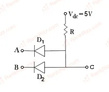
Two p-n junction diodes are connected as shown in figure. A and B are input signals and C is the output. The given circuit will function as a________.
NAND Gate
NOR Gate
AND Gate
OR Gate
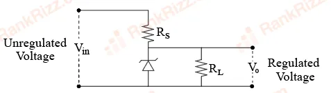
The following diagram shows a Zener diode as a voltage regulator. The Zener diode is rated at and the desired current in load is 5 mA. The unregulated voltage source can supply upto 25 V. Considering the Zener diode can withstand four times of the load current, the value of resistor (shown in circuit) should be ____ Ω .
10
4000
100
1000
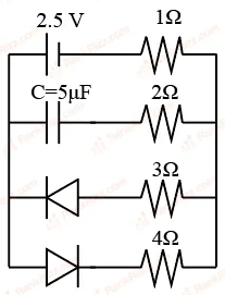
The charge stored by the capacitor C in the given circuit in the steady state is ______ .
7.5
5
10
12.5
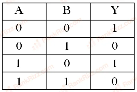
Identify the correct truth table of the given logic circuit.
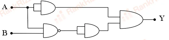
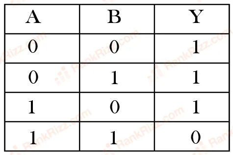
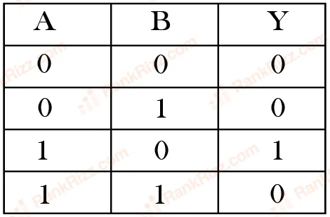
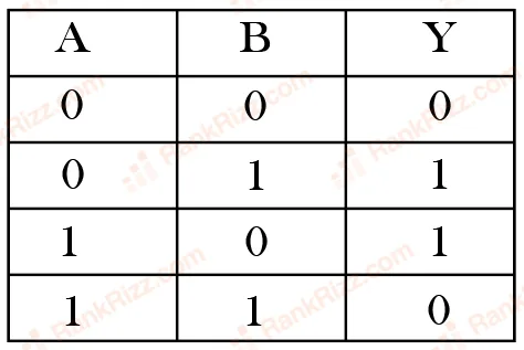
The given circuit works as:
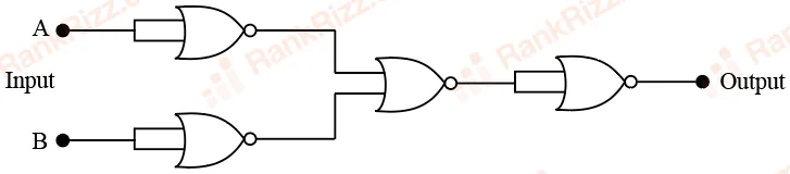
OR gate
NOR gate
NAND gate
AND gate
Find the correct combination of A, B, C and D inputs which can cause the LED to glow.
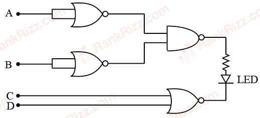
1000
0011
0100
1101
If X and Y are the inputs, the given circuit works as :
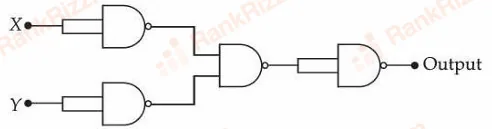
OR gate
AND gate
NAND gate
NOR gate
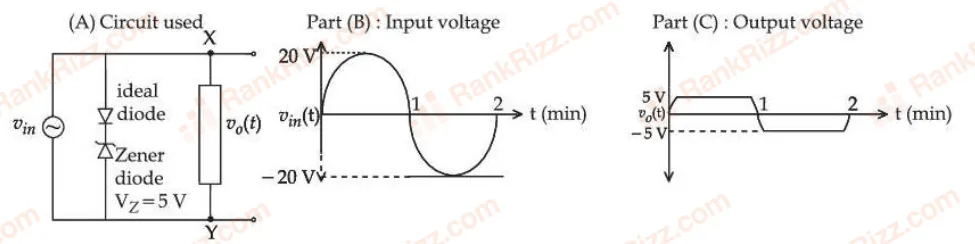
For the given circuit (shown in part (A)) the time dependent input voltage and corresponding output are shown in part (B) and part (C), respectively. Identify the components that are used in the circuit between points X and Y.




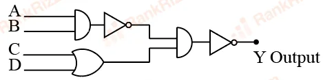
Two 4 bits binary numbers, and are given in the inputs of a logic circuit shown in figure below . The output will be :
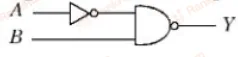
The correct truth table for the given input data of the following logic gate is:
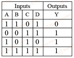
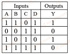
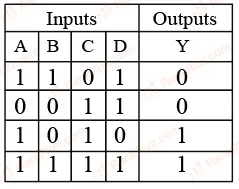
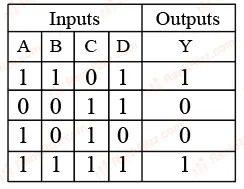
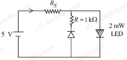
The maximum rated power of the LED is 2 mW and it is used in the circuit with input voltage of 5 V as shown in the figure below. The current through resistance is 0.5 mA.
The minimum value of the resistance of , to ensure that the LED is not damaged is _______ k.
6
2
4
5
Assuming in forward bias condition there is a voltage drop of 0.7V across a silicon diode, the current through diode in the circuit is ___ mA.
(Assume all diodes in the given circuit are identical)
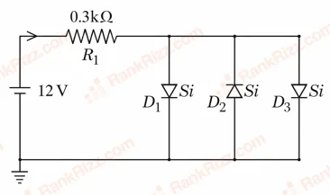
18.8
17.6
11.7
20.15
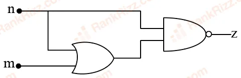
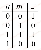
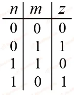
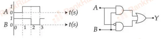
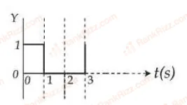
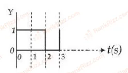
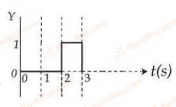
For the given logic gate circuit, which of the following is the correct truth table?
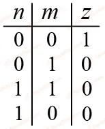
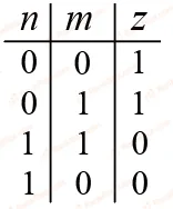
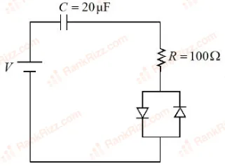
Consider a circuit consisting of a capacitor (20 F), resistor (100 ) and two identical diodes as shown in figure. The resistance of diode under forward biasing condition is 10 . The time constant of the circuit is s. The value of is :
Refer to the logic circuit given below. For two inputs and , output (Y) will be __________.
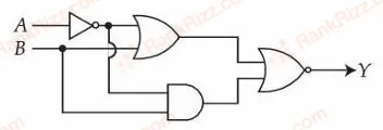
1, 0 respectively
0, 1 respectively
0, 0 respectively
1, 1 respectively
Given below are two statements: one is labelled as Assertion A and the other is labelled as Reason R
Assertion A: A diode under reverse-biased condition provides very small current which is nearly independent of voltage until a critical limit at which the current increases drastically.
Reason R: Below the critical voltage limit, only majority charge carriers flow which increases drastically above critical voltage.
Choose the correct answer from the options given below :
Both A and R are true, and R is the correct explanation of A
Both A and R are true, but R is NOT the correct explanation of A
A is true but R is false
A is false but R is true
In a semiconductor p-n diode, the doping concentrations on p-side has atoms/cm³ and the n-side has atoms/cm³respectively. Which one of the following statements is true?
Widths of depletion region on either side of the interface are equal
The depletion region widths is more on p-side compared to that in n-side
The depletion region width is more on n-side compared to that the p-side
No depletion region forms because of unequal doping concentrations on p and n-sides
The output for the given inputs and to the circuit is :
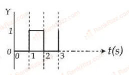
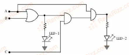
For the given logic circuit, which of the following inputs combination will make both LED-1 and LED-2 to glow?
OTHER PHYSICS CHAPTERS