RankRizz

Semiconductor Electronics — JEE Main Previous Year Questions

Every Semiconductor Electronics question JEE Main has set from 2004–2026, grouped by the idea it tests rather than the order of the syllabus. 253 questions across 6 distinct ideas. Free to read, answer key on every one.

Questions

253

Distinct ideas

6

Share of marks

4.4%

Difficulty

EASY

The ideas inside Semiconductor Electronics

A chapter is not one subject — it is a handful of procedures the examiner reuses. These are the ones Semiconductor Electronics questions actually test.

Every Semiconductor Electronics question

161–180 OF 253 · NEWEST FIRST

JEE MAIN 2020 · 03 SEP S2p-n junction diode and its characteristicsTRANSCRIBED

Which of the following will NOT be observed when a multimeter (operating in resistance measuring mode) probes connected across a component, are just reversed?

  1. A

    Multimeter shows an equal deflection in both cases i.e., before and after reversing the probes if the chosen component is resistor

  2. B

    Multimeter shows NO deflection in both cases i.e. before and after reversing the probes if the chosen component is capacitor

  3. C

    Multimeter shows a deflection, accompanied by a splash of light out of connected component in one direction and NO deflection on reversing the probes if the chosen component is LED

  4. D

    Multimeter shows NO deflection in both cases i.e. before and after reversing the probes is the chosen component is metal wire.
JEE MAIN 2020 · 03 SEP S1p-n junction diode and its characteristicsTRANSCRIBED

When a diode is forward biased, it has a voltage drop of 0.5 V. The safe limit of current through the diode is 10 mA. If a battery of emf 1.5 V is used in the circuit, the value of minimum resistance to be connected in series with the diode so that the current does not exceed the safe limit is:

  1. A

    300 Ω\Omega

  2. B

    50 Ω\Omega

  3. C

    100 Ω\Omega

  4. D

    200 Ω\Omega

JEE MAIN 2020 · 06 SEP S1Logic gates and digital circuitsTRANSCRIBED

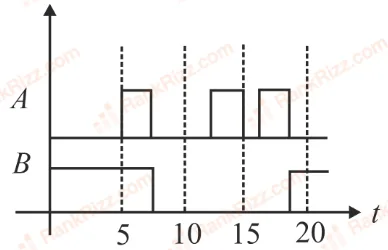
Identify the correct output signal YY in the given combination of gates (as shown nn) for the given inputs AA and BB:

Figure for JEE Main 2020 Physics question on Logic gates and digital circuitsFigure for JEE Main 2020 Physics question on Logic gates and digital circuits
  1. A
    Figure for JEE Main 2020 Physics question on Logic gates and digital circuits
  2. B
    Figure for JEE Main 2020 Physics question on Logic gates and digital circuits
  3. C
    Figure for JEE Main 2020 Physics question on Logic gates and digital circuits
  4. D
    Figure for JEE Main 2020 Physics question on Logic gates and digital circuits
JEE MAIN 2020 · 07 JAN S1Logic gates and digital circuitsTRANSCRIBED

Which of the following gives a reversible operation?

  1. A
    Figure for JEE Main 2020 Physics question on Logic gates and digital circuits
  2. B
    Figure for JEE Main 2020 Physics question on Logic gates and digital circuits
  3. C
    Figure for JEE Main 2020 Physics question on Logic gates and digital circuits
  4. D
    Figure for JEE Main 2020 Physics question on Logic gates and digital circuits
JEE MAIN 2020 · 05 SEP S1Zener diode, LED, photodiode and solar cellTRANSCRIBED

With increasing biasing voltage of a photo diode, the photocurrent magnitude:

  1. A

    remains constant

  2. B

    increases initially and after attaining certain value, it decreases

  3. C

    increases linearly

  4. D

    increases initially and saturates finally

JEE MAIN 2020 · 09 JAN S2Diode circuits and rectifiersTRANSCRIBED

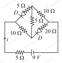
The current ii in the network is:

Figure for JEE Main 2020 Physics question on Diode circuits and rectifiers
  1. A

    0.2 A

  2. B

    0.6 A

  3. C

    0.3 A

  4. D

    0 A

JEE MAIN 2020 · 05 SEP S2Zener diode, LED, photodiode and solar cellTRANSCRIBED

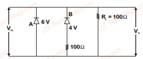
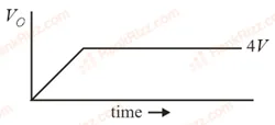
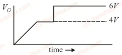
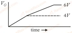
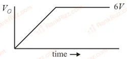
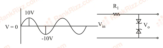
Two Zener diodes (AA and BB) having breakdown voltages of 6 V6\,\text{V} and 4 V4\,\text{V} respectively, are connected as shown in the circuit below. The output voltage V0V_0 variation with input voltage linearly increasing with time, is given by (Vinput=0VV_{input} = 0V at t=0t = 0):

Figure for JEE Main 2020 Physics question on Zener diode, LED, photodiode and solar cell
  1. A
    Figure for JEE Main 2020 Physics question on Zener diode, LED, photodiode and solar cell
  2. B
    Figure for JEE Main 2020 Physics question on Zener diode, LED, photodiode and solar cell
  3. C
    Figure for JEE Main 2020 Physics question on Zener diode, LED, photodiode and solar cell
  4. D
    Figure for JEE Main 2020 Physics question on Zener diode, LED, photodiode and solar cell
JEE MAIN 2020 · 03 SEP S2Zener diode, LED, photodiode and solar cellTRANSCRIBED

If a semiconductor photo diode can detect a photon with a maximum wavelength of 400 nm, then its band gap energy is: Planck's constant h = 6.63 ×\times 10−34^{-34} J.s, Speed of light c = 3 ×\times 108^8 m s−1^{-1}

  1. A

    1.1 eV

  2. B

    2.0 eV

  3. C

    1.5 eV

  4. D

    3.1 eV

JEE MAIN 2020 · 04 SEP S1Zener diode, LED, photodiode and solar cellTRANSCRIBED

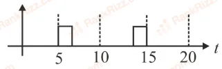
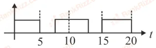
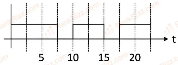
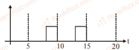
Take the breakdown voltage of the zener diode used in the given circuit as 6V. For the input voltage shown in the figure below, the time variation of the output voltage is: (Graphs drawn are schematic and not to the scale)

Figure for JEE Main 2020 Physics question on Zener diode, LED, photodiode and solar cell
  1. A
    Figure for JEE Main 2020 Physics question on Zener diode, LED, photodiode and solar cell
  2. B
    Figure for JEE Main 2020 Physics question on Zener diode, LED, photodiode and solar cell
  3. C
    Figure for JEE Main 2020 Physics question on Zener diode, LED, photodiode and solar cell
  4. D
    Figure for JEE Main 2020 Physics question on Zener diode, LED, photodiode and solar cell
JEE MAIN 2020 · 08 JAN S1Logic gates and digital circuitsTRANSCRIBED

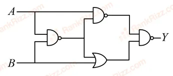
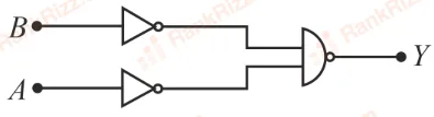
Boolean relation at the output stage Y for the following circuit is:

Figure for JEE Main 2020 Physics question on Logic gates and digital circuits
  1. A

    Aˉ+Bˉ\bar{A} + \bar{B}

  2. B

    A+BA + B

  3. C

    A⋅BA \cdot B

  4. D

    Aˉ⋅Bˉ\bar{A} \cdot \bar{B}

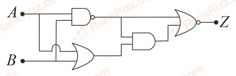
JEE MAIN 2020 · 02 SEP S2Logic gates and digital circuitsTRANSCRIBED

In the following digital circuit, what will be the output 'Z', when the input (A, B) are (1, 0), (0, 0), (1, 1), (0, 1):

Figure for JEE Main 2020 Physics question on Logic gates and digital circuits
  1. A

    0, 0, 1, 0

  2. B

    1, 0, 1, 1

  3. C

    1, 1, 0, 1

  4. D

    0, 1, 0, 0

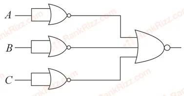
JEE MAIN 2020 · 04 SEP S2Logic gates and digital circuitsTRANSCRIBED

Identify the operation performed by the circuit given below:

Figure for JEE Main 2020 Physics question on Logic gates and digital circuits
  1. A

    NAND

  2. B

    OR

  3. C

    AND

  4. D

    NOT

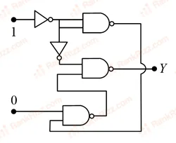
JEE MAIN 2020 · 08 JAN S2Logic gates and digital circuitsTRANSCRIBED

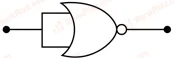
In the given circuit, value of Y is:

Figure for JEE Main 2020 Physics question on Logic gates and digital circuits
  1. A

    0

  2. B

    toggles between 0 and 1

  3. C

    will not execute

  4. D

    1

JEE MAIN 2020 · 09 JAN S1p-n junction diode and its characteristicsTRANSCRIBED

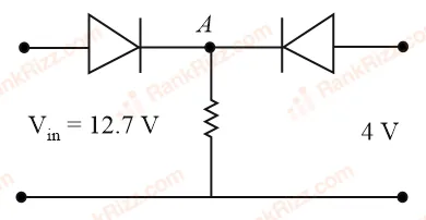
Both the diodes used in the circuit shown are assumed to be ideal and have negligible resistance when these are forward biased. Built in potential in each diode is 0.7V0.7V. For the input voltages shown in the figure, the voltage (in Volts) at point A is ___________.

Figure for JEE Main 2020 Physics question on p-n junction diode and its characteristics
JEE MAIN 2020 · 09 JAN S2Zener diode, LED, photodiode and solar cellTRANSCRIBED

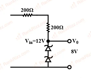
In the circuit shown below, is working as a 8 V dc regulated voltage source. When 12 V is used as an input, the power dissipated (in mW) in each diode is (Considering both zener diodes are identical) ___________.

Figure for JEE Main 2020 Physics question on Zener diode, LED, photodiode and solar cell
JEE MAIN 2020 · 06 SEP S2Transistors (older syllabus)TRANSCRIBED

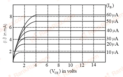
The output characteristics of a transistor is shown in the figure. When VCEV_{CE} is 10 V10\,\text{V} and IC=4.0 mAI_C = 4.0\,\text{mA}, then value of βac\beta_{ac} is___

Figure for JEE Main 2020 Physics question on Transistors (older syllabus)
JEE MAIN 2019 · 09 JAN S1p-n junction diode and its characteristicsTRANSCRIBED

Mobility of electrons in a semiconductor is defined as the ratio of their drift velocity to the applied electric field. If, for an N-type semiconductor, the density of electrons is 101910^{19} m−3^{-3} and their mobility is 1.6 m2^2 V−1^{-1} s−1^{-1}, then the resistivity of the semiconductor (since it is an N-type semiconductor contribution of holes is ignored) is close to:

  1. A

    0.2 Ω\Omega m

  2. B

    4 Ω\Omega m

  3. C

    2 Ω\Omega m

  4. D

    0.4 Ω\Omega m

JEE MAIN 2019 · 12 JAN S1Logic gates and digital circuitsTRANSCRIBED

The output of the given logic circuit is:

Figure for JEE Main 2019 Physics question on Logic gates and digital circuits
  1. A

    ABˉA\bar{B}

  2. B

    AˉB\bar{A}B

  3. C

    AB+AˉBAB + \bar{A}B

  4. D

    ABˉ+AˉBA\bar{B} + \bar{A}B

JEE MAIN 2019 · 11 JAN S1Zener diode, LED, photodiode and solar cellTRANSCRIBED

In the given circuit the current through Zener Diode is close to:

Figure for JEE Main 2019 Physics question on Zener diode, LED, photodiode and solar cell
  1. A

    0.0 mA

  2. B

    6.7 mA

  3. C

    4.0 mA

  4. D

    6.0 mA

JEE MAIN 2019 · 10 APR S1Transistors (older syllabus)TRANSCRIBED

An NPN transistor operates as a common emitter amplifier, with a power gain of 60 dB. The input circuit resistance is 100 Ω and the output load resistance is 10 kΩ. The common emitter current gain β is:

  1. A

    6×1026 \times 10^2

  2. B

    10210^2

  3. C

    10410^4

  4. D

    60