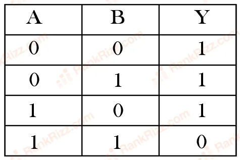
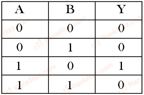
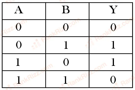
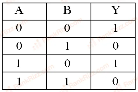
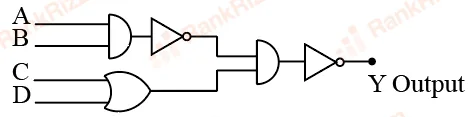
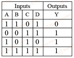
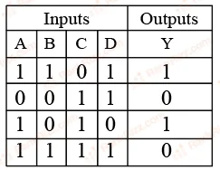
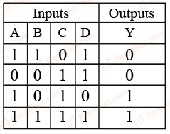
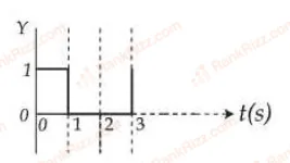
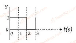
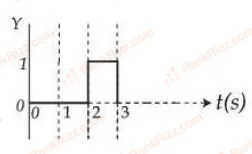
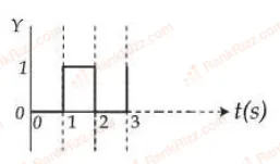
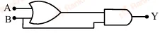
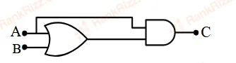
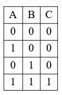
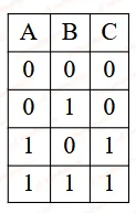
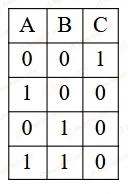
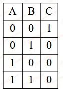
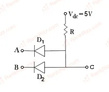
Two p-n junction diodes are connected as shown in figure. A and B are input signals and C is the output. The given circuit will function as a________.
- A
NAND Gate
- B
NOR Gate
- C
AND Gate
- D
OR Gate
Every JEE Main question on Logic gates and digital circuits, one of the ideas inside Semiconductor Electronics: 85 questions from 2008–2026, 46 of them in the last five years. Newest first, answer key on every one. Free to read.
Questions
85
Years asked
16
Since
2008
Of the chapter
34%
Questions on Logic gates and digital circuits in each year it was asked, the latest 12 of 16.
1–20 OF 85 · NEWEST FIRST
Two p-n junction diodes are connected as shown in figure. A and B are input signals and C is the output. The given circuit will function as a________.

NAND Gate
NOR Gate
AND Gate
OR Gate
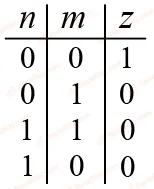
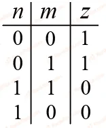
Identify the correct truth table of the given logic circuit.


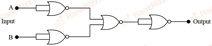
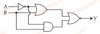
The given circuit works as:

OR gate
NOR gate
NAND gate
AND gate
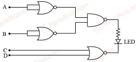
Find the correct combination of A, B, C and D inputs which can cause the LED to glow.

1000
0011
0100
1101
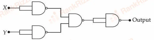
If X and Y are the inputs, the given circuit works as :

OR gate
AND gate
NAND gate
NOR gate
Two 4 bits binary numbers, and are given in the inputs of a logic circuit shown in figure below . The output will be :

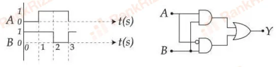
The correct truth table for the given input data of the following logic gate is:


For the given logic gate circuit, which of the following is the correct truth table?


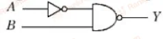
Refer to the logic circuit given below. For two inputs and , output (Y) will be __________.

1, 0 respectively
0, 1 respectively
0, 0 respectively
1, 1 respectively
The output for the given inputs and to the circuit is :


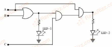
For the given logic circuit, which of the following inputs combination will make both LED-1 and LED-2 to glow?

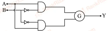
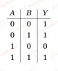
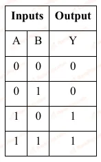
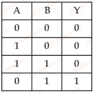
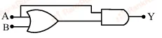
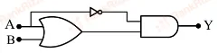
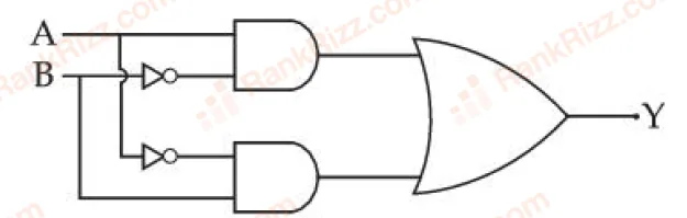
To obtain the given truth table, following logic gate should be placed at G:
OR Gate
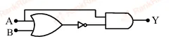
AND Gate
NOR Gate
NAND Gate
The output of the circuit is low (zero) for:
Choose the correct answer from the options given below:
(B), (C) and (D) only
(A), (B) and (C) only
(A), (C) and (D) only
(A), (B) and (D) only
Choose the correct logic circuit for the given truth table having inputs A and B.


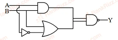
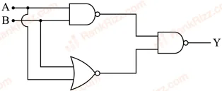
The truth table for the circuit given below is :


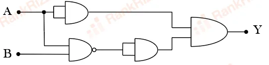
Consider the following logic circuit. The output is Y = 0 when :

A = 1 and B = 1
A = 0 and B = 1
A = 1 and B = 0
A = 0 and B = 0
For the circuit shown above, equivalent GATE is :
OR gate
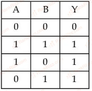
NAND gate
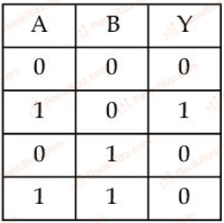
NOT gate
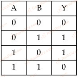
AND gate
The truth table corresponding to the circuit given below is


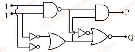
In the digital circuit shown in the figure, for the given inputs the P and Q values are :

The Boolean expression can be realised with which of the following gate configurations.
A. One 3-input AND gate, 3 NOT gates and one 2-input OR gate, One 2-input AND gate,
B. One 3-input AND gate, 1 NOT gate, One 2-input NOR gate and one 2-input OR gate
C. 3-input OR gate, 3 NOT gates and one 2-input AND gate
Choose the correct answer:
B, C Only
A, B Only
A, B, C Only
A, C Only