RankRizz

Semiconductor Electronics — JEE Main Previous Year Questions

Every Semiconductor Electronics question JEE Main has set from 2004–2026, grouped by the idea it tests rather than the order of the syllabus. 253 questions across 6 distinct ideas. Free to read, answer key on every one.

Questions

253

Distinct ideas

6

Share of marks

4.4%

Difficulty

EASY

The ideas inside Semiconductor Electronics

A chapter is not one subject — it is a handful of procedures the examiner reuses. These are the ones Semiconductor Electronics questions actually test.

Every Semiconductor Electronics question

21–40 OF 253 · NEWEST FIRST

JEE MAIN 2026 · 04 APR S2Zener diode, LED, photodiode and solar cellTRANSCRIBED

A diode has Zener voltage of 10 V and maximum power dissipation of 0.5 W, then the minimum resistance to be used in series with this diode for safety when it is connected to a 25 V power supply is ______ Ω\Omega.

JEE MAIN 2026 · 24 JAN S1Zener diode, LED, photodiode and solar cellTRANSCRIBED

A voltage regulating circuit consisting of Zener diode, having break-down voltage of 10 V and maximum power dissipation of 0.4 W, is operated at 15 V. The approximate value of protective resistance in this circuit is ___ Ω.

JEE MAIN 2025 · 22 JAN S2Logic gates and digital circuitsTRANSCRIBED
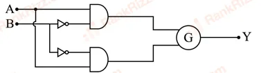
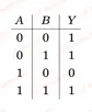
Figure for JEE Main 2025 Physics question on Logic gates and digital circuits Figure for JEE Main 2025 Physics question on Logic gates and digital circuits


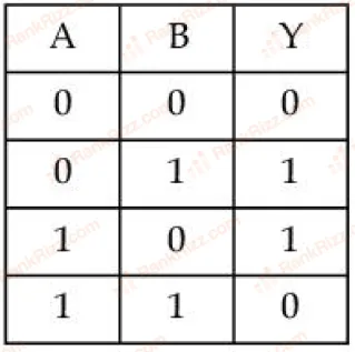
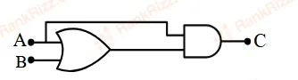
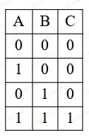
To obtain the given truth table, following logic gate should be placed at G:

  1. A

    OR Gate

  2. B

    AND Gate

  3. C

    NOR Gate

  4. D

    NAND Gate

JEE MAIN 2025 · 24 JAN S1Zener diode, LED, photodiode and solar cellTRANSCRIBED

Consider the following statements: A. The junction area of solar cell is made very narrow compared to a photo diode. B. Solar cells are not connected with any external bias. C. LED is made of lightly doped p-n junction. D. Increase of forward current results in continuous increase of LED light intensity. E. LEDs have to be connected in forward bias for emission of light. Choose the correct answer from the options given below:

  1. A

    B, E Only

  2. B

    B, D, E Only

  3. C

    A, C Only

  4. D

    A, C, E Only

JEE MAIN 2025 · 24 JAN S2Logic gates and digital circuitsTRANSCRIBED

The output of the circuit is low (zero) for:

page4_img1


(A)  X=0, Y=0 (B)  X=0, Y=1 (C)  X=1, Y=0 (D)  X=1, Y=1(A)\; X=0,\,Y=0 \text{ }(B)\; X=0,\,Y=1 \text{ }(C)\; X=1,\,Y=0 \text{ }(D)\; X=1,\,Y=1 Choose the correct answer from the options given below:

  1. A

    (B), (C) and (D) only

  2. B

    (A), (B) and (C) only

  3. C

    (A), (C) and (D) only

  4. D

    (A), (B) and (D) only

JEE MAIN 2025 · 03 APR S1Logic gates and digital circuitsTRANSCRIBED

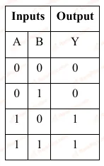
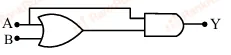
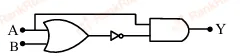
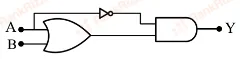
Choose the correct logic circuit for the given truth table having inputs A and B.

Figure for JEE Main 2025 Physics question on Logic gates and digital circuits
  1. A
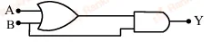
    Figure for JEE Main 2025 Physics question on Logic gates and digital circuits
  2. B
    Figure for JEE Main 2025 Physics question on Logic gates and digital circuits
  3. C
    Figure for JEE Main 2025 Physics question on Logic gates and digital circuits
  4. D
    Figure for JEE Main 2025 Physics question on Logic gates and digital circuits
JEE MAIN 2025 · 23 JAN S1Diode circuits and rectifiersTRANSCRIBED

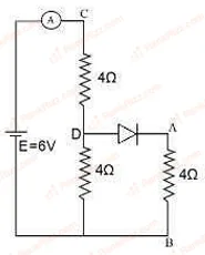
Refer to the circuit diagram given in the figure. which of the following observations are correct?

A. Total resistance of circuit is 6Ω6\Omega

B. Current in Ammeter is 1 A 

C. Potential across AB is 4 Volts.

D. Potential across CD is 4 Volts 

E. Total resistance of the circuit is 8Ω8\Omega . 

Choose the correct answer from the options given below:

page5_img1
  1. A

    A, B and D Only

  2. B

    A, B and C Only

  3. C

    A, C and D Only

  4. D

    B, C and E Only

JEE MAIN 2025 · 29 JAN S2Logic gates and digital circuitsTRANSCRIBED
page5_img1


The truth table for the circuit given below is :

  1. A
    page5_img2
  2. B
    page5_img3
  3. C
    page5_img4
  4. D
    page5_img5
JEE MAIN 2025 · 22 JAN S1p-n junction diode and its characteristicsTRANSCRIBED

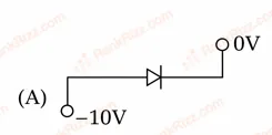
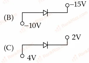
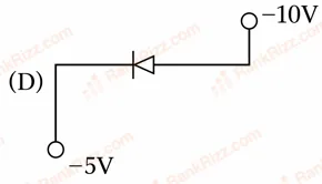
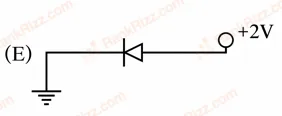
Which of the following circuits represents a forward biased diode?

Figure for JEE Main 2025 Physics question on p-n junction diode and its characteristics Figure for JEE Main 2025 Physics question on p-n junction diode and its characteristics Figure for JEE Main 2025 Physics question on p-n junction diode and its characteristics Figure for JEE Main 2025 Physics question on p-n junction diode and its characteristics

Choose the correct answer from the options given below :

  1. A

    (A) and (D) only

  2. B

    (B), (D) and (E) only

  3. C

    (C) and (E) only

  4. D

    (B), (C) and (E) only

JEE MAIN 2025 · 08 APR S2p-n junction diode and its characteristicsTRANSCRIBED

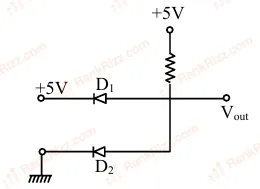
The output voltage in the following circuit is (Consider ideal diode case) :

Figure for JEE Main 2025 Physics question on p-n junction diode and its characteristics
  1. A

    10 V

  2. B

    0 V

  3. C

    +5 V

  4. D

    -5 V

JEE MAIN 2025 · 23 JAN S2Diode circuits and rectifiersTRANSCRIBED

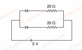
What is the current through the battery in the circuit shown below

Figure for JEE Main 2025 Physics question on Diode circuits and rectifiers
  1. A

    1.5 A

  2. B

    0.5 A

  3. C

    0.25 A

  4. D

    1.0 A

JEE MAIN 2025 · 07 APR S2Logic gates and digital circuitsTRANSCRIBED

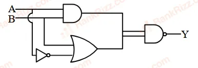
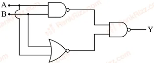
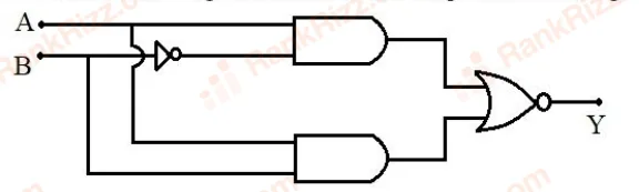
Consider the following logic circuit. The output is Y = 0 when :

Figure for JEE Main 2025 Physics question on Logic gates and digital circuits
  1. A

    A = 1 and B = 1

  2. B

    A = 0 and B = 1

  3. C

    A = 1 and B = 0

  4. D

    A = 0 and B = 0

JEE MAIN 2025 · 02 APR S1Zener diode, LED, photodiode and solar cellTRANSCRIBED

A zener diode with 5V zener voltage is used to regulate an unregulated dc voltage input of 25 V. For a 400 Ω\Omega resistor connected in series, the zener current is found to be 4 times load current. The load current (ILI_L) and load resistance (RLR_L) are:

  1. A

    ILI_L = 20 mA; RLR_L = 250 Ω\Omega

  2. B

    ILI_L = 10 A; RLR_L = 0.5 Ω\Omega

  3. C

    ILI_L = 0.02 mA; RLR_L = 250 Ω\Omega

  4. D

    ILI_L = 10 mA; RLR_L = 500 Ω\Omega

JEE MAIN 2025 · 07 APR S1Zener diode, LED, photodiode and solar cellTRANSCRIBED

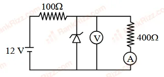
In the following circuit, the reading of the ammeter will be (Take Zener breakdown voltage = 4 V)

Figure for JEE Main 2025 Physics question on Zener diode, LED, photodiode and solar cell
  1. A

    24 mA

  2. B

    80 mA

  3. C

    10 mA

  4. D

    60 mA

JEE MAIN 2025 · 29 JAN S1Logic gates and digital circuitsTRANSCRIBED
Figure for JEE Main 2025 Physics question on Logic gates and digital circuits


For the circuit shown above, equivalent GATE is :

  1. A

    OR gate

  2. B

    NAND gate

  3. C

    NOT gate

  4. D

    AND gate

JEE MAIN 2025 · 03 APR S2Logic gates and digital circuitsTRANSCRIBED

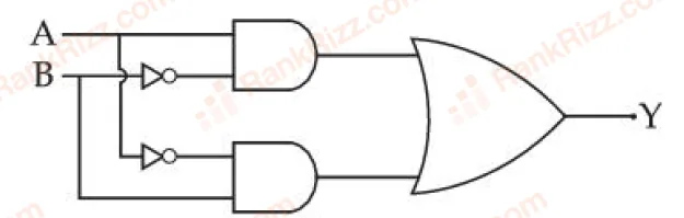
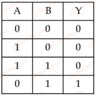
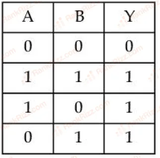
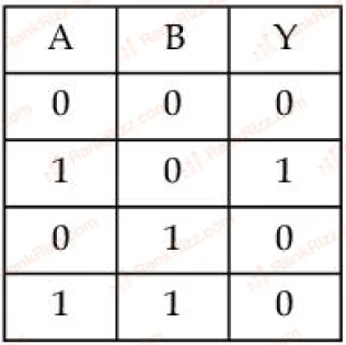
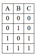
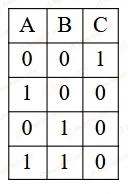
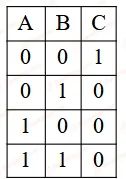
The truth table corresponding to the circuit given below is

Figure for JEE Main 2025 Physics question on Logic gates and digital circuits
  1. A
    Figure for JEE Main 2025 Physics question on Logic gates and digital circuits
  2. B
    Figure for JEE Main 2025 Physics question on Logic gates and digital circuits
  3. C
    Figure for JEE Main 2025 Physics question on Logic gates and digital circuits
  4. D
    Figure for JEE Main 2025 Physics question on Logic gates and digital circuits
JEE MAIN 2025 · 02 APR S2Logic gates and digital circuitsTRANSCRIBED

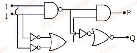
In the digital circuit shown in the figure, for the given inputs the P and Q values are :

Figure for JEE Main 2025 Physics question on Logic gates and digital circuits
  1. A

    P=1,Q=1P = 1, Q = 1

  2. B

    P=0,Q=0P = 0, Q = 0

  3. C

    P=0,Q=1P = 0, Q = 1

  4. D

    P=1,Q=0P = 1, Q = 0

JEE MAIN 2025 · 04 APR S1Logic gates and digital circuitsTRANSCRIBED

The Boolean expression Y=A‾BC+A‾CY = \overline{A}BC + \overline{A}C can be realised with which of the following gate configurations.
A. One 3-input AND gate, 3 NOT gates and one 2-input OR gate, One 2-input AND gate,
B. One 3-input AND gate, 1 NOT gate, One 2-input NOR gate and one 2-input OR gate
C. 3-input OR gate, 3 NOT gates and one 2-input AND gate
Choose the correct answer:

  1. A

    B, C Only

  2. B

    A, B Only

  3. C

    A, B, C Only

  4. D

    A, C Only

JEE MAIN 2025 · 04 APR S2p-n junction diode and its characteristicsTRANSCRIBED

Consider a n-type semiconductor in which nen_e and nhn_h are number of electrons and holes, respectively.
(A) Holes are minority carriers
(B) The dopant is a pentavalent atom
(C) nenh≠ni2n_e n_h \neq n_i^2
       (where nin_{i} is number of electrons or holes in semiconductor when it is intrinsic form)
(D) nenh≥ni2n_e n_h \geq n_i^2
(E) The holes are not generated due to the donors
Choose the correct answer from the options given below :

  1. A

    (A), (C), (D) only

  2. B

    (A), (C), (E) only

  3. C

    (A), (B), (E) only

  4. D

    (A), (B), (C) only

JEE MAIN 2025 · 28 JAN S1Logic gates and digital circuitsTRANSCRIBED

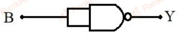
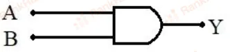
Which of the following circuits has the same output as that of the given circuit?

page7_img2
  1. A
    page7_img3
  2. B
    page7_img4
  3. C
    page7_img5
  4. D
    page7_img6