RankRizz

Logic gates and digital circuits — JEE Main Previous Year Questions

Every JEE Main question on Logic gates and digital circuits, one of the ideas inside Semiconductor Electronics: 85 questions from 2008–2026, 46 of them in the last five years. Newest first, answer key on every one. Free to read.

Questions

85

Years asked

16

Since

2008

Of the chapter

34%

Every Logic gates and digital circuits question

41–60 OF 85 · NEWEST FIRST

JEE MAIN 2023 · 11 APR S2Logic gates and digital circuitsTRANSCRIBED

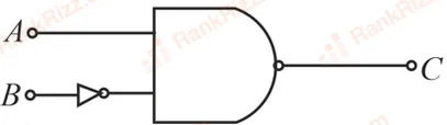
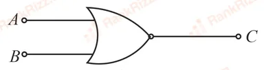
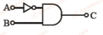
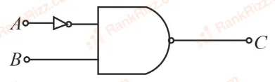
The logic operations performed by the given digital circuit is equivalent to:
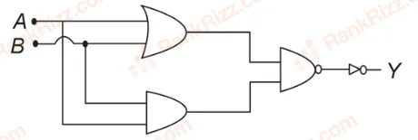
Figure for JEE Main 2023 Physics question on Logic gates and digital circuits
  1. A

    NOR

  2. B

    AND

  3. C

    OR

  4. D

    NAND

JEE MAIN 2022 · 28 JUN S1Logic gates and digital circuitsTRANSCRIBED

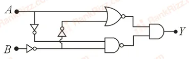
In the following circuit, the correct relation between output (YY) and inputs AA and BB will be

Figure for JEE Main 2022 Physics question on Logic gates and digital circuits
  1. A

    Y=A⋅BY = A \cdot B

  2. B

    Y=A +BY = A + B

  3. C

    Y=A⋅B‾Y = \overline{A \cdot B}

  4. D

    Y=A+B‾Y = \overline{A + B}

JEE MAIN 2022 · 25 JUN S2Logic gates and digital circuitsTRANSCRIBED

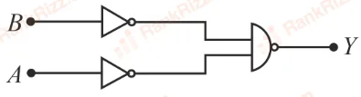
Identify the logic operation performed by the given circuit
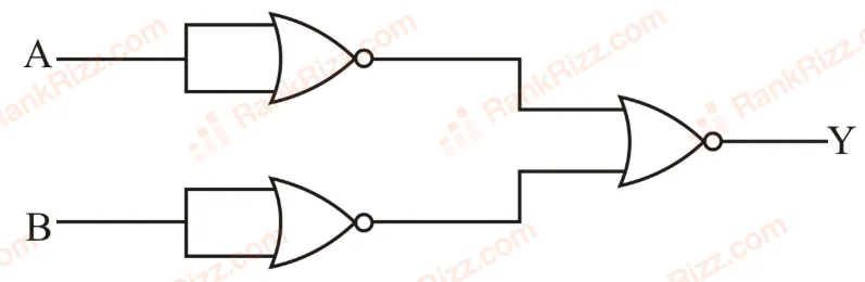
Figure for JEE Main 2022 Physics question on Logic gates and digital circuits
  1. A

    AND gate

  2. B

    OR gate

  3. C

    NOR gate

  4. D

    NAND gate

JEE MAIN 2022 · 27 JUL S1Logic gates and digital circuitsTRANSCRIBED

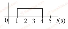
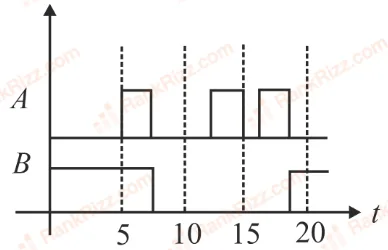
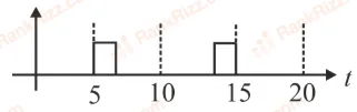
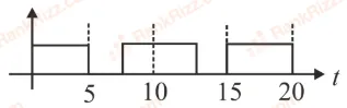
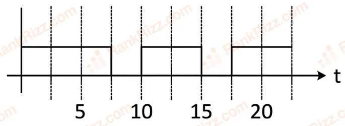
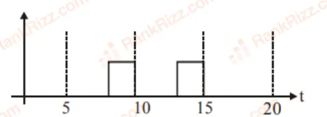
A logic gate circuit has two inputs AA and BB and output YY. The voltage waveforms of AA, BB and YY are shown. The logic gate circuit is

Figure for JEE Main 2022 Physics question on Logic gates and digital circuits
  1. A

    AND gate

  2. B

    OR gate

  3. C

    NOR gate

  4. D

    NAND gate

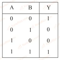
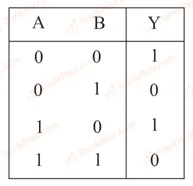
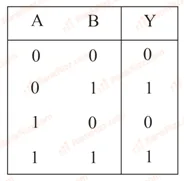
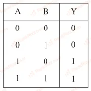
JEE MAIN 2022 · 27 JUN S1Logic gates and digital circuitsTRANSCRIBED

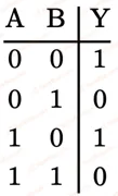
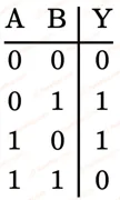
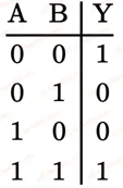
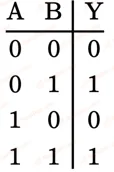
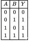
Identify the correct Logic Gate for the following output (YY) of two inputs AA and BB.

Figure for JEE Main 2022 Physics question on Logic gates and digital circuits
  1. A
    Figure for JEE Main 2022 Physics question on Logic gates and digital circuits
  2. B
    Figure for JEE Main 2022 Physics question on Logic gates and digital circuits
  3. C
    Figure for JEE Main 2022 Physics question on Logic gates and digital circuits
  4. D
    Figure for JEE Main 2022 Physics question on Logic gates and digital circuits
JEE MAIN 2022 · 25 JUL S1Logic gates and digital circuitsTRANSCRIBED

In the circuit, the logical value of A=1A = 1 or B=1B = 1 when potential at AA or BB is 5 V5 \text{ V} and the logical value of A=0A = 0 or B=0B = 0 when potential at AA or BB is 0 V0 \text{ V}.

Figure for JEE Main 2022 Physics question on Logic gates and digital circuits

The truth table of the given circuit will be:

  1. A

    ABY000100010111\begin{array}{|c|c|c|}\hline A & B & Y \\ \hline 0 & 0 & 0 \\ 1 & 0 & 0 \\ 0 & 1 & 0 \\ 1 & 1 & 1 \\ \hline \end{array}

  2. B

    ABY000101011111\begin{array}{|c|c|c|}\hline A & B & Y \\ \hline 0 & 0 & 0 \\ 1 & 0 & 1 \\ 0 & 1 & 1 \\ 1 & 1 & 1 \\ \hline \end{array}

  3. C

    ABY000100010110\begin{array}{|c|c|c|}\hline A & B & Y \\ \hline 0 & 0 & 0 \\ 1 & 0 & 0 \\ 0 & 1 & 0 \\ 1 & 1 & 0 \\ \hline \end{array}

  4. D

    ABY001101011110\begin{array}{|c|c|c|}\hline A & B & Y \\ \hline 0 & 0 & 1 \\ 1 & 0 & 1 \\ 0 & 1 & 1 \\ 1 & 1 & 0 \\ \hline \end{array}

JEE MAIN 2021 · 24 FEB S2Logic gates and digital circuitsTRANSCRIBED

The logic circuit shown above is equivalent to:
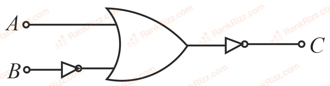
Figure for JEE Main 2021 Physics question on Logic gates and digital circuits
  1. A
    Figure for JEE Main 2021 Physics question on Logic gates and digital circuits
  2. B
    Figure for JEE Main 2021 Physics question on Logic gates and digital circuits
  3. C
    Figure for JEE Main 2021 Physics question on Logic gates and digital circuits
  4. D
    Figure for JEE Main 2021 Physics question on Logic gates and digital circuits
JEE MAIN 2021 · 25 FEB S2Logic gates and digital circuitsTRANSCRIBED

The truth table for the following logic circuit is:
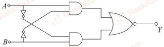
Figure for JEE Main 2021 Physics question on Logic gates and digital circuits
  1. A
    Figure for JEE Main 2021 Physics question on Logic gates and digital circuits
  2. B
    Figure for JEE Main 2021 Physics question on Logic gates and digital circuits
  3. C
    Figure for JEE Main 2021 Physics question on Logic gates and digital circuits
  4. D
    Figure for JEE Main 2021 Physics question on Logic gates and digital circuits
JEE MAIN 2021 · 26 AUG S1Logic gates and digital circuitsTRANSCRIBED

Identify the logic operation carried out by the given circuit:
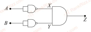
Figure for JEE Main 2021 Physics question on Logic gates and digital circuits
  1. A

    OR

  2. B

    AND

  3. C

    NAND

  4. D

    NOR

JEE MAIN 2021 · 16 MAR S2Logic gates and digital circuitsTRANSCRIBED

The following logic gate is equivalent to:
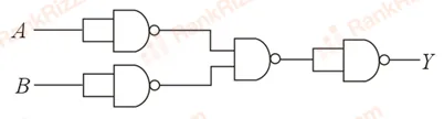
Figure for JEE Main 2021 Physics question on Logic gates and digital circuits
  1. A

    NOR Gate

  2. B

    OR Gate

  3. C

    AND Gate

  4. D

    NAND Gate

JEE MAIN 2021 · 17 MAR S1Logic gates and digital circuitsTRANSCRIBED

The output of the given combination gates represents:
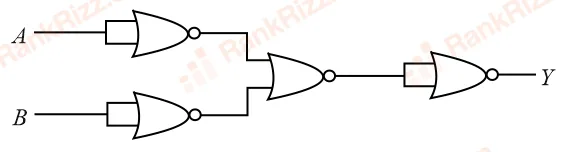
Figure for JEE Main 2021 Physics question on Logic gates and digital circuits
  1. A

    XOR Gate

  2. B

    NAND Gate

  3. C

    AND Gate

  4. D

    NOR Gate

JEE MAIN 2021 · 31 AUG S2Logic gates and digital circuitsTRANSCRIBED

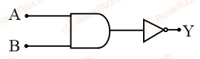
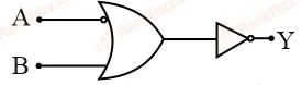
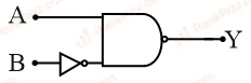
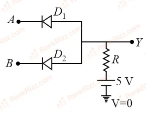
If VAV_A and VBV_B are the input voltages (either 5 V or 0 V) and V0V_0 is the output voltage then the two gates represented in the following circuits A and B are:
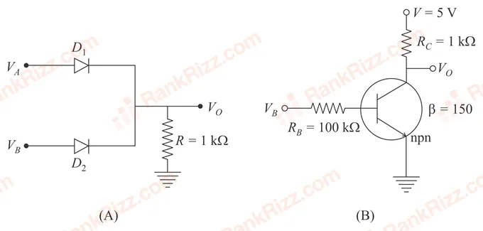
Figure for JEE Main 2021 Physics question on Logic gates and digital circuits
  1. A

    OR and NOT Gate

  2. B

    AND and NOT Gate

  3. C

    AND and OR Gate

  4. D

    NAND and NOR Gate

JEE MAIN 2021 · 17 MAR S2Logic gates and digital circuitsTRANSCRIBED

Which one of the following will be the output of the given circuit?

Figure for JEE Main 2021 Physics question on Logic gates and digital circuits
  1. A

    NOR Gate

  2. B

    NAND Gate

  3. C

    AND Gate

  4. D

    XOR Gate

JEE MAIN 2021 · 26 AUG S2Logic gates and digital circuitsTRANSCRIBED

Four NOR gates are connected as shown in figure. The truth table for the given figure is:
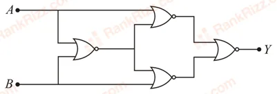
Figure for JEE Main 2021 Physics question on Logic gates and digital circuits
  1. A
    Figure for JEE Main 2021 Physics question on Logic gates and digital circuits
  2. B
    Figure for JEE Main 2021 Physics question on Logic gates and digital circuits
  3. C
    Figure for JEE Main 2021 Physics question on Logic gates and digital circuits
  4. D
    Figure for JEE Main 2021 Physics question on Logic gates and digital circuits
JEE MAIN 2021 · 25 JUL S1Logic gates and digital circuitsTRANSCRIBED

Identify the logic operation carried out.
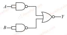
Figure for JEE Main 2021 Physics question on Logic gates and digital circuits
  1. A

    OR

  2. B

    AND

  3. C

    NOR

  4. D

    NAND

JEE MAIN 2021 · 31 AUG S1Logic gates and digital circuitsTRANSCRIBED

In the following logic circuit the sequence of the inputs AA, BB are (0,0),(0,1),(1,0)(0, 0), (0, 1), (1, 0) and (1,1)(1, 1). The output YY for this sequence will be:

Figure for JEE Main 2021 Physics question on Logic gates and digital circuits
  1. A

    0, 1, 0, 1

  2. B

    0, 0, 1, 1

  3. C

    1, 1, 1, 0

  4. D

    1, 0, 1, 0

JEE MAIN 2021 · 27 JUL S2Logic gates and digital circuitsTRANSCRIBED

Find the truth table for the function Y of A and B represented in the following figure.
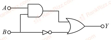
Figure for JEE Main 2021 Physics question on Logic gates and digital circuits
  1. A
    Figure for JEE Main 2021 Physics question on Logic gates and digital circuits
  2. B
    Figure for JEE Main 2021 Physics question on Logic gates and digital circuits
  3. C
    Figure for JEE Main 2021 Physics question on Logic gates and digital circuits
  4. D
    Figure for JEE Main 2021 Physics question on Logic gates and digital circuits
JEE MAIN 2021 · 26 FEB S2Logic gates and digital circuitsTRANSCRIBED

Draw the output signal Y in the given combination of gates.
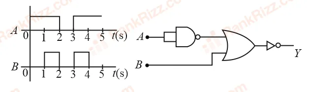
Figure for JEE Main 2021 Physics question on Logic gates and digital circuits
  1. A
    Figure for JEE Main 2021 Physics question on Logic gates and digital circuits
  2. B
    Figure for JEE Main 2021 Physics question on Logic gates and digital circuits
  3. C
    Figure for JEE Main 2021 Physics question on Logic gates and digital circuits
  4. D
    Figure for JEE Main 2021 Physics question on Logic gates and digital circuits
JEE MAIN 2021 · 16 MAR S1Logic gates and digital circuitsTRANSCRIBED

In the logic circuit shown in the figure, if input AA and BB are 0 to 1 respectively, the output at YY would be xx. The value of xx is ________.

Figure for JEE Main 2021 Physics question on Logic gates and digital circuits
JEE MAIN 2020 · 06 SEP S1Logic gates and digital circuitsTRANSCRIBED

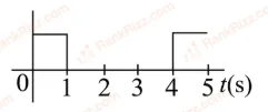
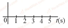
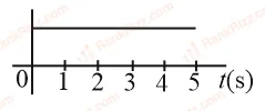
Identify the correct output signal YY in the given combination of gates (as shown nn) for the given inputs AA and BB:

Figure for JEE Main 2020 Physics question on Logic gates and digital circuitsFigure for JEE Main 2020 Physics question on Logic gates and digital circuits
  1. A
    Figure for JEE Main 2020 Physics question on Logic gates and digital circuits
  2. B
    Figure for JEE Main 2020 Physics question on Logic gates and digital circuits
  3. C
    Figure for JEE Main 2020 Physics question on Logic gates and digital circuits
  4. D
    Figure for JEE Main 2020 Physics question on Logic gates and digital circuits