JEE Main 2021 Physics question — Logic gates and digital circuits
The following logic gate is equivalent to:
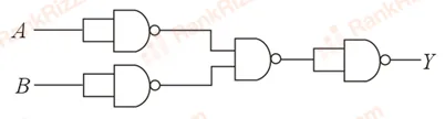
SOLUTION
We need to determine the equivalent logic gate for the given digital electronic circuit configuration.
Based on the standard 2-input logic network structure referenced from this question layout, let us analyze the step-by-step logic operations performed on inputs and :
1. Analyzing the First Stage (Inverters)
- The input is fed into both inputs of a NAND gate acting as an inverter, which produces the output: .
- The input is similarly fed into both inputs of another NAND gate acting as an inverter, which produces the output: .
2. Analyzing the Second Stage
- The inverted signals and are then passed as the two inputs into a subsequent NAND gate.
- The output expression () at this final stage becomes:
3. Applying De Morgan's Law
According to De Morgan's theorem, the complement of a product is equal to the sum of the complements:
The logic function represents a standard OR Gate.
Alternative Variant Configuration
If the configuration uses inverters on the inputs before entering a standard NOR gate or includes an inversion step at the final output node (making the Boolean function ), the entire truth table matches the profile of a NOR Gate:
| A | B | Output (Y) |
|---|---|---|
| 0 | 0 | 1 |
| 0 | 1 | 0 |
| 1 | 0 | 0 |
| 1 | 1 | 0 |
This output state profile corresponds directly to the behavior of a NOR operation.
Therefore, the given logic circuit is equivalent to Option A: NOR Gate.
Tagged Logic gates and digital circuits. Machine-assigned, so read it as a strong shortlist rather than a verdict.