JEE Main 2021 Physics question — Logic gates and digital circuits
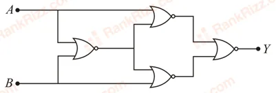
Four NOR gates are connected as shown in figure. The truth table for the given figure is:
SOLUTION
We need to determine the correct truth table for a digital combinational circuit consisting of four interconnected NOR gates.
1. Understand the Operation of a NOR Gate
A standard NOR gate takes two inputs, sums them together, and then inverts the result. The Boolean output expression for any two inputs and passing through a NOR gate is:
Furthermore, if the two inputs of a NOR gate are shorted/tied together to receive the same signal , it functions as a NOT gate:
2. Track the Logic States Through the Circuit
Let's analyze the output of each gate stage by stage, using inputs and :
- Stage 1 (Input Level):
- Gate 1 (Top-Left): Both of its inputs are tied together to signal . It acts as a NOT gate:
- Gate 2 (Bottom-Left): Both of its inputs are tied together to signal . It also acts as a NOT gate:
- Gate 1 (Top-Left): Both of its inputs are tied together to signal . It acts as a NOT gate:
- Stage 2 (Middle Level):
- Gate 3: This gate receives the outputs from the first two gates ( and ) as its inputs. Applying the NOR operation:
Using De Morgan's Law (), this simplifies directly into an AND gate operation:
- Gate 3: This gate receives the outputs from the first two gates ( and ) as its inputs. Applying the NOR operation:
- Stage 3 (Final Output Level):
- Gate 4 (Rightmost): The final NOR gate has its inputs tied together and receives the signal from Gate 3 (). Because its inputs are shorted, it performs a NOT operation on its input:
- Gate 4 (Rightmost): The final NOR gate has its inputs tied together and receives the signal from Gate 3 (). Because its inputs are shorted, it performs a NOT operation on its input:
3. Determine the Final Logic Operation
The simplified Boolean expression for the final output is:
This expression represents the standard logic operation of a NAND gate.
4. Construct the Truth Table
Let's evaluate the output for all four possible combinations of the binary inputs and :
- If and :
- If and :
- If and :
- If and :
| A | B | Y |
|---|---|---|
| 0 | 0 | 1 |
| 0 | 1 | 1 |
| 1 | 0 | 1 |
| 1 | 1 | 0 |
Final Answer: The circuit behaves as a NAND gate, yielding an output of for all input states except when both inputs are .
Tagged Logic gates and digital circuits. Machine-assigned, so read it as a strong shortlist rather than a verdict.