JEE Main 2021 Physics question — Logic gates and digital circuits
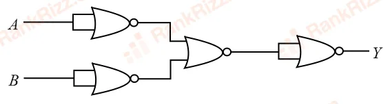
The output of the given combination gates represents:
SOLUTION
We need to determine the logic function represented by the given combination of logic gates.
1. Analyze the Individual Gates
From the schematic on , let's trace the logic level from left to right:
- First Stage (Input Inverters):
The two gates at the input have their pins shorted together. A NOR gate with tied inputs functions exactly as a NOT gate.
- Output of the top gate:
- Output of the bottom gate:
- Second Stage (Middle NOR Gate):
The inverted inputs and are fed into a third NOR gate. The output expression at this stage is:
Using De Morgan's Law ():
- Third Stage (Final Output Inverter):
The signal passes through a final NOR gate that also has its inputs shorted together, acting as another NOT gate:
2. Identify the Resulting Boolean Expression
The overall output Boolean expression is:
This expression represents the standard logic operation of a NAND Gate.
Conclusion
The output of the given combination of gates represents a NAND Gate, which corresponds to Option B.
Tagged Logic gates and digital circuits. Machine-assigned, so read it as a strong shortlist rather than a verdict.