JEE MAIN 2021 · 25 FEB S2+4 / −1EASYTRANSCRIBED
JEE Main 2021 Physics question — Logic gates and digital circuits
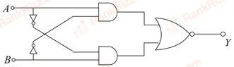
The truth table for the following logic circuit is:
SOLUTION
Solution & Explanation
1. Trace the Inputs to the AND Gates
Let's track the binary signals moving from the input terminals through the branches:
- Top AND Gate:
- The upper input branch connects directly to the line coming from terminal .
- The lower input branch passes through an inverter (NOT gate) connected crosswise from terminal , which yields .
- Thus, the expression for the upper gate's output is:
- Bottom AND Gate:
- The upper input branch passes through an inverter (NOT gate) connected crosswise from terminal , which yields .
- The lower input branch connects directly to the line coming from terminal .
- Thus, the expression for the lower gate's output is:
2. Evaluate the Final NOR Gate
Both of these intermediate outputs flow directly into a two-input NOR gate at the final stage. A NOR gate adds its inputs together (OR operation) and then inverts the entire sum:
Notice that the inner term represents a standard XOR gate function (). Since it is inverted by the outer overbar, the complete expression is equivalent to an XNOR gate ():
3. Construct the Truth Table
An XNOR gate outputs a high logical state () only when both inputs match each other (i.e., both are or both are ):
| 0 | 0 | 0 | 0 | 0 | 1 |
| 0 | 1 | 0 | 1 | 1 | 0 |
| 1 | 0 | 1 | 0 | 1 | 0 |
| 1 | 1 | 0 | 0 | 0 | 1 |
Correct Option: The truth table option displaying output states sequentially from top to bottom is correct ..
Tagged Logic gates and digital circuits. Machine-assigned, so read it as a strong shortlist rather than a verdict.