RankRizz

Electromagnetic Induction — JEE Main Previous Year Questions

Every Electromagnetic Induction question JEE Main has set from 2004–2026, grouped by the idea it tests rather than the order of the syllabus. 178 questions across 6 distinct ideas. Free to read, answer key on every one.

Questions

178

Distinct ideas

6

Share of marks

3.8%

Difficulty

MEDIUM

The ideas inside Electromagnetic Induction

A chapter is not one subject — it is a handful of procedures the examiner reuses. These are the ones Electromagnetic Induction questions actually test.

Every Electromagnetic Induction question

161–178 OF 178 · NEWEST FIRST

JEE MAIN 2013 · 09 APR ONLINESelf inductance and energy stored in inductorsTRANSCRIBED

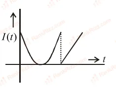
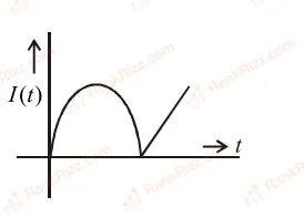
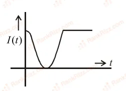
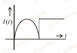
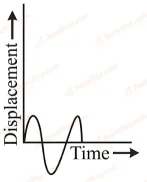
Two coils, X and Y, are kept in close vicinity of each other. When a varying current, I(t)I(t), flows through coil X, the induced emf (V(t))(V(t)) in coil Y, varies in the manner shown here. The variation of I(t)I(t), with time, can then be represented by the graph labelled as graph :
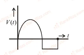
Figure for JEE Main 2013 Physics question on Self inductance and energy stored in inductors Figure for JEE Main 2013 Physics question on Self inductance and energy stored in inductors

(A)

Figure for JEE Main 2013 Physics question on Self inductance and energy stored in inductors

(B)

Figure for JEE Main 2013 Physics question on Self inductance and energy stored in inductors

(c)

Figure for JEE Main 2013 Physics question on Self inductance and energy stored in inductors

(D)

  1. A

    A

  2. B

    C

  3. C

    B

  4. D

    D

JEE MAIN 2012Emf in rotating rods, discs and coils; eddy currentsTRANSCRIBED

A coil is suspended in a uniform magnetic field, with the plane of the coil parallel to the magnetic lines of force. When a current is passed through the coil it starts oscillating; it is very difficult to stop. But if an aluminium plate is placed near to the coil, it stops. This is due to :

  1. A

    development of air current when the plate is placed.

  2. B

    induction of electrical charge on the plate

  3. C

    shielding of magnetic lines of force as aluminium is a paramagnetic material.

  4. D

    electromagnetic induction in the aluminium plate giving rise to electromagnetic damping.

JEE MAIN 2012Motional emf in moving rods and loopsTRANSCRIBED

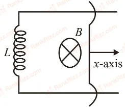
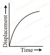
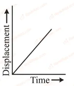
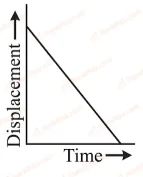
A coil of self inductance LL is connected at one end of two rails as shown in figure. A connector of length ll, mass mm can slide freely over the two parallel rails. The entire set up is placed in a magnetic field of induction BB going into the page. At an instant t=0t=0 an initial velocity v0v_0 is imparted to it and as a result of that it starts moving along xx-axis. The displacement of the connector is represented by the figure.

Figure for JEE Main 2012 Physics question on Motional emf in moving rods and loops
  1. A
    Figure for JEE Main 2012 Physics question on Motional emf in moving rods and loops
  2. B
    Figure for JEE Main 2012 Physics question on Motional emf in moving rods and loops
  3. C
    Figure for JEE Main 2012 Physics question on Motional emf in moving rods and loops
  4. D
    Figure for JEE Main 2012 Physics question on Motional emf in moving rods and loops
JEE MAIN 2012Self inductance and energy stored in inductorsTRANSCRIBED

This question has Statement 1 and Statement 2. Of the four choices given after the Statements, choose the one that best describes the two Statements. Statement 1: Self inductance of a long solenoid of length LL, total number of turns NN and radius rr is less than πμ0N2r2L\frac{\pi\mu_0 N^2 r^2}{L}. Statement 2: The magnetic induction in the solenoid in Statement 1 carrying current II is μ0NIL\frac{\mu_0 NI}{L} in the middle of the solenoid but becomes less as we move towards its ends.

  1. A

    Statement 1 is true, Statement 2 is false.

  2. B

    Statement 1 is true, Statement 2 is true, Statement 2 is the correct explanation of Statement 1.

  3. C

    Statement 1 is false, Statement 2 is true.

  4. D

    Statement 1 is true, Statement 2 is true, Statement 2 is not the correct explanation of Statement 1.

JEE MAIN 2012Magnetic flux, Faraday's law and Lenz's lawTRANSCRIBED

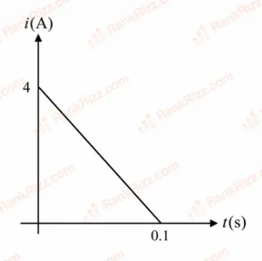
Magnetic flux through a coil of resistance 10Ω10\Omega is changed by Δϕ\Delta\phi in 0.10.1 s. The resulting current in the coil varies with time as shown in the figure. Then ∣Δϕ∣|\Delta\phi| is equal to (in weber)

Figure for JEE Main 2012 Physics question on Magnetic flux, Faraday's law and Lenz's law
  1. A

    66

  2. B

    44

  3. C

    22

  4. D

    88

JEE MAIN 2011Motional emf in moving rods and loopsTRANSCRIBED

A boat is moving due east in a region where the earth's magnetic field is 5.0×10⁻⁵ NA−1m−15.0 \times 10^{-5} \, \text{NA}^{-1} \text{m}^{-1} due north and horizontal. The boat carries a vertical aerial 2 m2 \, \text{m} long. If the speed of the boat is 1.50 ms−11.50 \, \text{ms}^{-1}, the magnitude of the induced emf in the wire of aerial is:

  1. A

    0.75 mV0.75 \, \text{mV}

  2. B

    0.50 mV0.50 \, \text{mV}

  3. C

    0.15 mV0.15 \, \text{mV}

  4. D

    1 mV1 \, \text{mV}

JEE MAIN 2010Motional emf in moving rods and loopsTRANSCRIBED

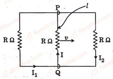
A rectangular loop has a sliding connector PQ of length ℓ\ell and resistance RΩR\Omega and it is moving with a speed vv as shown. The set-up is placed in a uniform magnetic field going into the plane of the paper. The three currents I1,I2I_1, I_2 and II are
Figure for JEE Main 2010 Physics question on Motional emf in moving rods and loops

  1. A

    I1=−I2=BℓvR,I=2BℓvRI_1 = -I_2 = \frac{B\ell v}{R}, I = \frac{2 B\ell v}{R}

  2. B

    I1=I2=Bℓv3R,I=2Bℓv3RI_1 = I_2 = \frac{B\ell v}{3R}, I = \frac{2 B\ell v}{3R}

  3. C

    I1=I2=I=BℓvRI_1 = I_2 = I = \frac{B\ell v}{R}

  4. D

    I1=I2=Bℓv6R,I=Bℓv3RI_1 = I_2 = \frac{B\ell v}{6R}, I = \frac{B\ell v}{3R}

JEE MAIN 2010LR circuits: growth and decay of currentTRANSCRIBED

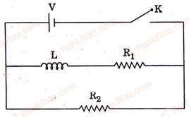
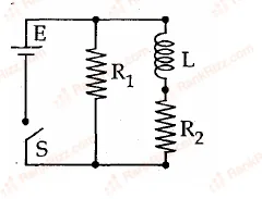
In the circuit shown below, the key K is closed at t=0t = 0. The current through the battery is

Figure for JEE Main 2010 Physics question on LR circuits: growth and decay of current
  1. A

    VR1R2R12+R22\frac{V R_1 R_2}{\sqrt{R_1^2 + R_2^2}} at t=0t = 0 and VR2\frac{V}{R_2} at t=∞t = \infty

  2. B

    VR2\frac{V}{R_2} at t=0t = 0 and V(R1+R2)R1R2\frac{V(R_1 + R_2)}{R_1 R_2} at t=∞t = \infty

  3. C

    VR2\frac{V}{R_2} at t=0t = 0 and VR1R2R12+R22\frac{V R_1 R_2}{\sqrt{R_1^2 + R_2^2}} at t=∞t = \infty

  4. D

    V(R1+R2)R1R2\frac{V(R_1 + R_2)}{R_1 R_2} at t=0t = 0 and VR2\frac{V}{R_2} at t=∞t = \infty

JEE MAIN 2009LR circuits: growth and decay of currentTRANSCRIBED

An inductor of inductance L=400L = 400 mH and resistors of resistances R1=2ΩR_1 = 2\Omega and R2=2ΩR_2 = 2\Omega are connected to a battery of emf 1212 V as shown in the figure. The internal resistance of the battery is negligible. The switch SS is Figure for JEE Main 2009 Physics question on LR circuits: growth and decay of current closed at t=0t = 0. The potential drop across LL as a function of time is

  1. A

    6e−5t6e^{-5t} V

  2. B

    12te−3t\frac{12}{t}e^{-3t} V

  3. C

    6(1−e−t/0.2)6\left(1 - e^{-t/0.2}\right) V

  4. D

    12e−5t12e^{-5t} V

JEE MAIN 2008Mutual inductanceTRANSCRIBED

Two coaxial solenoids are made by winding thin insulated wire over a pipe of cross sectional area A=10 cm2A = 10\ cm^2 and length = 20 cm. If one of the solenoids has 300 turns and the other 400 turns, their mutual inductance is (μ0=4π×10−7 T m A−1)(\mu_0 = 4\pi \times 10^{-7}\ T\ m\ A^{-1})

  1. A

    2.4π×10−5 H2.4\pi \times 10^{-5}\ H

  2. B

    4.8π×10−4 H4.8\pi \times 10^{-4}\ H

  3. C

    4.8π×10−5 H4.8\pi \times 10^{-5}\ H

  4. D

    2.4π×10−4 H2.4\pi \times 10^{-4}\ H

JEE MAIN 2007LR circuits: growth and decay of currentTRANSCRIBED

An ideal coil of 10H10 H is connected in series with a resistance of 5Ω5 \Omega and a battery of 5V5 V. 2 second after the connection is made the current flowing in amperes in the circuit is

  1. A

    (1−e)(1 - e)

  2. B

    ee

  3. C

    e−1e^{-1}

  4. D

    (1−e−1)(1 - e^{-1})

JEE MAIN 2006Magnetic flux, Faraday's law and Lenz's lawTRANSCRIBED

The flux linked with a coil at any instant 'tt' is given by ϕ=10t2−50t+250\phi = 10t^2 - 50t + 250. The induced emf at t=3 st = 3\,s is

  1. A

    190 V

  2. B

    −190-190 V

  3. C

    −10-10 V

  4. D

    10 V

JEE MAIN 2006LR circuits: growth and decay of currentTRANSCRIBED

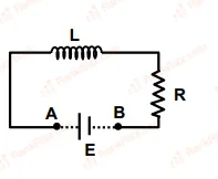
An inductor (L=100 mH)(L = 100\,mH), a resistor (R=100 Ω)(R = 100\,\Omega) and a battery (E=100 V)(E = 100\,V) are initially connected in series as shown in the figure. After a long time the battery is disconnected after short circuiting the points AA and BB.

Figure for JEE Main 2006 Physics question on LR circuits: growth and decay of current

What is the  current in the circuit  after 1 ms1\,ms ?

  1. A

    1 A

  2. B

    1/e A1/e\,A

  3. C

    e Ae\,A

  4. D

    0.1 A

JEE MAIN 2005Motional emf in moving rods and loopsTRANSCRIBED

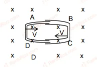
One conducting U tube can slide inside another as shown in figure, maintaining electrical contacts between the tubes. The magnetic field BB is perpendicular to the plane of the figure. If each tube moves towards the other at a constant speed VV, then the emf induced in the circuit in terms of BB, ℓ\ell and VV where ℓ\ell is the width of each tube will be Figure for JEE Main 2005 Physics question on Motional emf in moving rods and loops

  1. A

    BℓVB \ell V

  2. B

    −BℓV-B \ell V

  3. C

    zero

  4. D

    2BℓV2 B \ell V

JEE MAIN 2005LR circuits: growth and decay of currentTRANSCRIBED

A coil of inductance 300300 mH and resistance 2Ω2 \Omega is connected to a source of voltage 22 V. The current reaches half of its steady state value in

  1. A

    0.050.05 s

  2. B

    0.10.1 s

  3. C

    0.150.15 s

  4. D

    0.30.3 s

JEE MAIN 2004Magnetic flux, Faraday's law and Lenz's lawTRANSCRIBED

A coil having nn turns and resistance 4RΩ4R\Omega. This combination is moved in time tt seconds from a magnetic field W1W_1 weber to W2W_2 weber. The induced current in the circuit is

  1. A

    −W2−W15Rnt-\frac{W_2 - W_1}{5Rnt}

  2. B

    −n(W2−W1)5Rt-\frac{n(W_2 - W_1)}{5Rt}

  3. C

    −W2−W1Rnt-\frac{W_2 - W_1}{Rnt}

  4. D

    −n(W2−W1)Rt-\frac{n(W_2 - W_1)}{Rt}

JEE MAIN 2004Emf in rotating rods, discs and coils; eddy currentsTRANSCRIBED

In a uniform magnetic field of induction BB a wire in the form of semicircle of radius rr rotates about the diameter of the circle with angular frequency ω\omega. The axis of rotation is perpendicular to the field. If the total resistance of the circuit is RR the mean power generated per period of rotation is

  1. A

    Bπr2ω2R\frac{B\pi r^2 \omega}{2R}

  2. B

    (Bπr2ω)22R\frac{(B\pi r^2 \omega)^2}{2R}

  3. C

    (Bπrω)22R\frac{(B\pi r \omega)^2}{2R}

  4. D

    (Bπrω2)28R\frac{(B\pi r \omega^2)^2}{8R}

JEE MAIN 2004Emf in rotating rods, discs and coils; eddy currentsTRANSCRIBED

A metal conductor of length 11 m rotates vertically about one of its ends at angular velocity 55 radians per second. If the horizontal component of earth's magnetic field is 0.3×10−40.3 \times 10^{-4} T, then the e.m.f. developed between the two ends of the conductor is

  1. A

    5×10−95 \times 10^{-9} V

  2. B

    5×10−55 \times 10^{-5} V

  3. C

    50μ50\muV

  4. D

    5μ5\muV