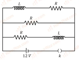
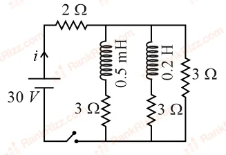
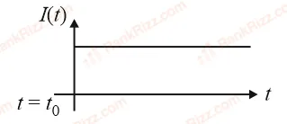
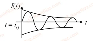
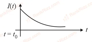
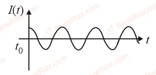
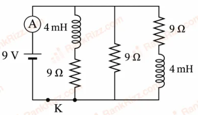
Figure shows the circuit that contains three resistances (9 each) and two inductors (4 mH each). The reading of ammeter at the moment switch K is turned ON, is ____ A.
- A
2
- B
1
- C
3
- D
zero
Every JEE Main question on LR circuits: growth and decay of current, one of the ideas inside Electromagnetic Induction: 29 questions from 2005–2026, 9 of them in the last five years. Newest first, answer key on every one. Free to read.
Questions
29
Years asked
15
Since
2005
Of the chapter
16%
Questions on LR circuits: growth and decay of current in each year it was asked, the latest 12 of 15.
1–20 OF 29 · NEWEST FIRST
Figure shows the circuit that contains three resistances (9 each) and two inductors (4 mH each). The reading of ammeter at the moment switch K is turned ON, is ____ A.

2
1
3
zero
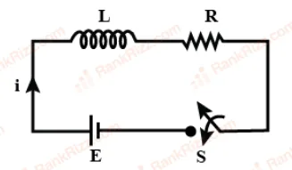
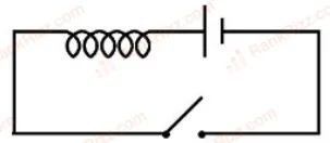
An inductor of inductance 10 mH having resistance of 100 is connected to battery of E.M.F. 1.0 V through a switch as shown in the figure below. After switch is closed, the ratio of instantaneous voltages across the inductor when the current passing through it is 2 mA and 4 mA is _______.

4/3
3/4
5/3
3/5
A capacitor of capacitance is charged to a potential of V and connected to a mH inductor to produce oscillations. The maximum current in the circuit would be :
A
A
A
A
In the given figure, an inductor and resistor are connected in series with a battery of emf volt. J s represents the maximum rate at which the energy is stored in the magnetic field (inductor). The numerical value of will be _____.

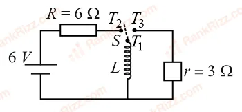
Three identical resistors with resistance and two identical inductors with self inductance mH are connected to an ideal battery with emf of 12 V as shown in figure. The current through the battery long after the switch has been closed will be _____ A.

An oscillating LC circuit consists of a 75 mH inductor and a 1.2 F capacitor. If the maximum charge to the capacitor is 2.7 C. The maximum current in the circuit will be ______ mA.
A coil has an inductance of 2 H and resistance of 4 . A 10 V is applied across the coil. The energy stored in the magnetic field after the current has built up to its equilibrium value will be _______ J
A coil of inductance 1 H and resistance 100 is connected to a battery of 6 V. Determine approximately:
(a) The time elapsed before the current acquires half of its steady-state value
(b) The energy stored in the magnetic field associated with the coil at an instant 15 ms after the circuit is switched on.
(Given , )
ms; mJ
ms; mJ
ms; mJ
ms; mJ
A capacitor of capacitance 500 F is charged completely using a DC supply of 100 V. It is now connected to an inductor of inductance 50 mH to form an LC circuit. The maximum current in LC circuit will be _____ A.
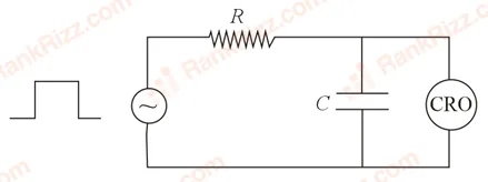
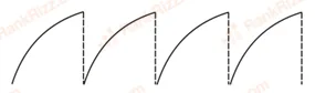
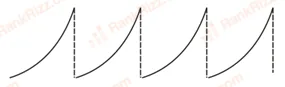
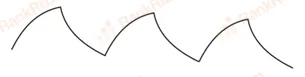
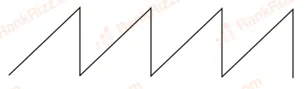
An circuit as shown in the figure is driven by a source generating a square wave. The output wave pattern monitored by would look close to:


For the given circuit the current through the battery when the key is closed and the steady state has been reached is:

10 A
6 A
25 A
0 A
Consider an electrical circuit containing a two way switch . Initially is open and then is connected to . As the current in attains a maximum value of steady-state level, is disconnected from and immediately connected to . Potential drop across resistor immediately after is connected to is _________ V. (Round off to the Nearest Integer)

An inductor of 10 mH is connected to a 20 V battery through a resistor of 10 k and a switch. After a long time, when maximum current is set up in the circuit, the current is switched off. The current in the circuit after 1 s is mA. Then is equal to ___. (Take )
An emf of 20 V is applied at time to a circuit containing in series 10 mH inductor and 5 resistor. The ratio of the currents at time and at s is close to: (Take )
1.06
1.15
1.46
0.84
A series circuit is connected to a battery of emf . If the circuit is switched on at , then the time at which the energy stored in the inductor reaches times of its maximum value, is:
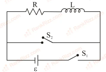
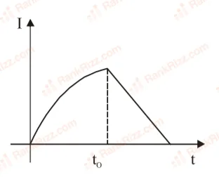
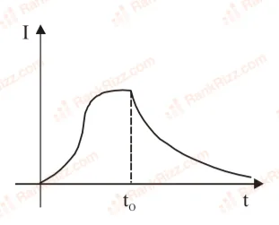
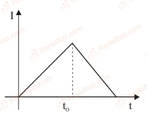
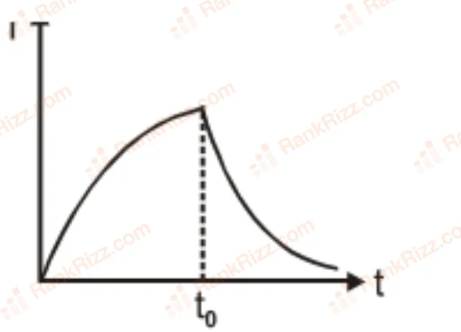
In the circuit shown, the switch is closed at time and the switch is kept open. At some later time , the switch is opened and is closed. The behaviour of the current I as a function of time t is given by:


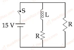
In the figure shown, a circuit contains two identical resistors with resistance and an inductance with mH. An ideal battery of 15V is connected in the circuit. What will be the current through the battery long after the switch is closed?

5.5 A
6 A
3 A
7.5 A
Consider the LR circuit shown in the figure. If the switch S is closed at t = 0 then the amount of charge that passes through the battery between t = 0 and t = is:

A coil of self inductance 10 mH and resistance of 0.1 Ω is connected through a switch to a battery of internal resistance 0.9 Ω. After the switch is closed, the time taken for the current to attain 80% of the saturation value is: [ln5 = 1.6]
0.103 s
0.002 s
0.324 s
0.016 s
A series circuit is connected to a voltage source with . After a very large time, current behaves as :