RankRizz

Series LCR circuits: impedance and phase — JEE Main Previous Year Questions

Every JEE Main question on Series LCR circuits: impedance and phase, one of the ideas inside Alternating Current: 121 questions from 2004–2026, 76 of them in the last five years. Newest first, answer key on every one. Free to read.

Questions

121

Years asked

15

Since

2004

Of the chapter

73%

Every Series LCR circuits: impedance and phase question

101–120 OF 121 · NEWEST FIRST

JEE MAIN 2021 · 25 FEB S1Series LCR circuits: impedance and phaseTRANSCRIBED

A transmitting station releases waves of wavelength 960 m. A capacitor of 2.56 μ\muF is used in the resonant circuit. The self-inductance of coil necessary for resonance is x×10−8x \times 10^{-8} H. Find xx.

JEE MAIN 2020 · 07 JAN S1Series LCR circuits: impedance and phaseTRANSCRIBED

A LCR circuit behaves like a clamped harmonic oscillator. Comparing it with a physical spring-mass damped oscillator having damping constant 'b', the correct equivalence would be:

  1. A

    L↔m,C↔k,R↔bL \leftrightarrow m, C \leftrightarrow k, R \leftrightarrow b

  2. B

    L↔1b,C↔1m,R↔1kL \leftrightarrow \frac{1}{b}, C \leftrightarrow \frac{1}{m}, R \leftrightarrow \frac{1}{k}

  3. C

    L↔k,C↔b,R↔mL \leftrightarrow k, C \leftrightarrow b, R \leftrightarrow m

  4. D

    L↔m,C↔1k,R↔bL \leftrightarrow m, C \leftrightarrow \frac{1}{k}, R \leftrightarrow b

JEE MAIN 2020 · 03 SEP S1Series LCR circuits: impedance and phaseTRANSCRIBED

A 750 Hz, 20 V(rms) source is connected to a resistance of 100 Ω\Omega, an inductance of 0.1803 H and a capacitance of 10 μ\muF all in series. The time in which the resistance (heat capacity 2 J/°C) will get heated by 10°C (assume no loss of heat to the surroundings) is close to:

  1. A

    418 s

  2. B

    245 s

  3. C

    365 s

  4. D

    348 s

JEE MAIN 2020 · 09 JAN S2Series LCR circuits: impedance and phaseTRANSCRIBED

In LCLC circuit the inductance L=40L = 40 mH and capacitance C=100C = 100 μ\muF. If a voltage V(t)=10sin⁡(314t)V(t) = 10\sin(314t) is applied to the circuit, the current in the circuit is given as:

  1. A

    0.52 cos(314t)

  2. B

    10 cos(314t)

  3. C

    5.2 cos(314t)

  4. D

    0.52 sin(314t)

JEE MAIN 2020 · 02 SEP S2Series LCR circuits: impedance and phaseTRANSCRIBED

An inductance coil has a reactance of 100 Ω\Omega. When an AC signal of frequency 1000 Hz is applied to the coil, the applied voltage leads the current by 45°°. The self-inductance of the coil is:

  1. A

    1.1×10−21.1 \times 10^{-2} H

  2. B

    1.1×10−11.1 \times 10^{-1} H

  3. C

    5.5×10−55.5 \times 10^{-5} H

  4. D

    6.7×10−76.7 \times 10^{-7} H

JEE MAIN 2020 · 06 SEP S2Series LCR circuits: impedance and phaseTRANSCRIBED

In a series LR circuit, power of 400 W400\,\text{W} is dissipated from a source of 250 V250\,\text{V}, 50 Hz50\,\text{Hz}. The power factor of the circuit is 0.80.8. In order to bring the power factor to unity, a capacitor of value C is added in series to the L and R. Taking the value of C as (n3π) μF\left(\frac{n}{3\pi}\right)\,\mu F, then value of n is___

JEE MAIN 2019 · 12 JAN S2Series LCR circuits: impedance and phaseTRANSCRIBED
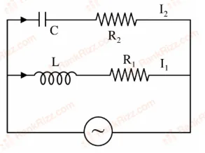
Figure for JEE Main 2019 Physics question on Series LCR circuits: impedance and phase

In the above circuit, C=32μFC = \frac{\sqrt{3}}{2}\mu F, R2=20ΩR_2 = 20 \Omega, L=310HL = \frac{\sqrt{3}}{10} H and R1=10ΩR_1 = 10 \Omega. Current in LL-R1R_1 path is I1I_1 and in C-R2R_2 path it is I2I_2. The voltage of AC source is given by, V=2002sin⁡(100t)V = 200\sqrt{2} \sin(100t) volts. The phase difference between I1I_1 and I2I_2 is:

  1. A

    60°

  2. B

    0°

  3. C

    30°

  4. D

    150°

JEE MAIN 2019 · 08 APR S1Series LCR circuits: impedance and phaseTRANSCRIBED

An alternating voltage V(t)=220sin⁡(100πt)V(t) = 220\sin(100\pi t) volt is applied to a purely resistive load of 50 Ω\Omega. The time taken for the current to rise from half of the peak value to the peak value is:

  1. A

    7.21 ms

  2. B

    5.25 ms

  3. C

    2.24 ms

  4. D

    3.33 ms

JEE MAIN 2019 · 09 JAN S2Series LCR circuits: impedance and phaseTRANSCRIBED

A series AC circuit containing an inductor (20 mH), a capacitor (120 μ\muF) and a resistor (60 Ω\Omega) is driven by an AC source of 24 V/50 Hz. The energy dissipated in the circuit in 60 s is:

  1. A

    5.17×1025.17 \times 10^2 J

  2. B

    3.39×1033.39 \times 10^3 J

  3. C

    2.26×1032.26 \times 10^3 J

  4. D

    5.65×1025.65 \times 10^2 J

JEE MAIN 2019 · 08 APR S2Series LCR circuits: impedance and phaseTRANSCRIBED

A circuit connected to an ac source of emf e=e0sin⁡(100t)e = e_0 \sin(100t) with t in seconds, gives a phase difference of π4\frac{\pi}{4} between the emf ee and current ii. Which of the following circuits will exhibit this?

  1. A

    RC circuit with R = 1 kΩ\Omega and C = 1 μ\muF

  2. B

    RL circuit with R = 1 kΩ\Omega and L = 1 mH

  3. C

    RL circuit with R = 1 kΩ\Omega and L = 10 mH

  4. D

    RC circuit with R = 1 kΩ\Omega and C = 10 μ\muF

JEE MAIN 2017 · 09 APR ONLINESeries LCR circuits: impedance and phaseTRANSCRIBED

A sinusoidal voltage of peak value 283 V and angular frequency 320 s−1^{-1} is applied to a series LCR circuit. Given that R=5  ΩR = 5 \; \Omega, L=25L = 25 mH and C=1000  μC = 1000 \; \muF. The total impedance and phase difference between the voltage across the source and the current will respectively be-

  1. A

    10 Ω\Omega and tan⁡−1(53)\tan^{-1}\left(\frac{5}{3}\right)

  2. B

    7 Ω\Omega and 45°

  3. C

    7 Ω\Omega and tan⁡−1(53)\tan^{-1}\left(\frac{5}{3}\right)

  4. D

    10 Ω\Omega and tan⁡−1(83)\tan^{-1}\left(\frac{8}{3}\right)

JEE MAIN 2016 · 03 APR OFFLINESeries LCR circuits: impedance and phaseTRANSCRIBED

An arc lamp requires a direct current of 10 A at 80 V to function. If it is connected to a 220 V (rms), 50 Hz AC supply, the series inductor needed for it to work is close to:

  1. A

    0.044 H

  2. B

    0.065 H

  3. C

    80 H

  4. D

    0.08 H

JEE MAIN 2015 · 11 APR ONLINESeries LCR circuits: impedance and phaseTRANSCRIBED

The AC voltage across a resistance can be measured using a:

  1. A

    Moving magnet galvanometer

  2. B

    Moving coil galvanometer

  3. C

    Hot wire voltmeter

  4. D

    Potentiometer

JEE MAIN 2015 · 11 APR ONLINESeries LCR circuits: impedance and phaseTRANSCRIBED

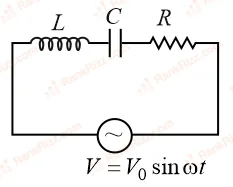
For the LCR circuit, shown here, the current is observed to lead the applied voltage. An additional capacitor C′C', when joined with the capacitor C present in the circuit, makes the power factor of the circuit unity. The capacitor C′C', must have been connected in:

Figure for JEE Main 2015 Physics question on Series LCR circuits: impedance and phase
  1. A

    Parallel with C and has a magnitude 1−ω2LCω2L\frac{1-\omega^2LC}{\omega^2 L}

  2. B

    Series with C and has a magnitude 1−ω2LCω2L\frac{1-\omega^2LC}{\omega^2 L}

  3. C

    Series with C and has a magnitude C(ω2LC−1)\frac{C}{(\omega^2LC-1)}

  4. D

    Parallel with C and has a magnitude C(ω2LC−1)\frac{C}{(\omega^2LC-1)}

JEE MAIN 2014 · 09 APR ONLINESeries LCR circuits: impedance and phaseTRANSCRIBED

When the rms voltages VLV_L, VCV_C and VRV_R are measured respectively across the inductor L, the capacitor C and the resistor R in a series LCR circuit connected to an AC source, it is found that the ratio VL:VC:VR=1:2:3V_L : V_C : V_R = 1 : 2 : 3. If the rms voltage of the AC source is 100 V, then VRV_R is close to:

  1. A

    50 V

  2. B

    70 V

  3. C

    100 V

  4. D

    95 V

JEE MAIN 2013 · 25 APR ONLINESeries LCR circuits: impedance and phaseTRANSCRIBED

When resonance is produced in a series LCR circuit, then which of the following is not correct?

  1. A

    Current in the circuit is in phase with the applied voltage.

  2. B

    Inductive and capacitive reactances are equal.

  3. C

    If R is reduced, the voltage across capacitor will increase.

  4. D

    Impedance of the circuit is maximum.

JEE MAIN 2013 · 22 APR ONLINESeries LCR circuits: impedance and phaseTRANSCRIBED

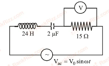
An LCR circuit as shown in the figure is connected to a voltage source VacV_{ac} whose frequency can be varied. The frequency, at which the voltage across the resistor is maximum, is :

Figure for JEE Main 2013 Physics question on Series LCR circuits: impedance and phase
  1. A

    902 Hz

  2. B

    143 Hz

  3. C

    23 Hz

  4. D

    345 Hz

JEE MAIN 2013 · 25 APR ONLINESeries LCR circuits: impedance and phaseTRANSCRIBED

A series LR circuit is connected to an ac source of frequency ω\omega and the inductive reactance is equal to 2R. A capacitance of capacitive reactance equal to R is added in series with L and R. The ratio of the new power factor to the old one is :

  1. A

    23\sqrt{\frac{2}{3}}

  2. B

    25\sqrt{\frac{2}{5}}

  3. C

    32\sqrt{\frac{3}{2}}

  4. D

    52\sqrt{\frac{5}{2}}

JEE MAIN 2013 · 09 APR ONLINESeries LCR circuits: impedance and phaseTRANSCRIBED

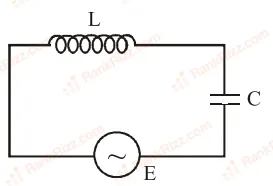
In the circuit shown here, the voltage across E and C are respectively 300 V and 400 V. The voltage E of the ac source is :

Figure for JEE Main 2013 Physics question on Series LCR circuits: impedance and phase
  1. A

    400 Volt

  2. B

    500 Volt

  3. C

    100 Volt

  4. D

    700 Volt

JEE MAIN 2012Series LCR circuits: impedance and phaseTRANSCRIBED

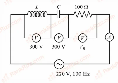
In an LCRLCR circuit shown in the following figure, what will be the readings of the voltmeter across the resistor and ammeter if an a.c. source of 220 V and 100 Hz is connected to it as shown?

Figure for JEE Main 2012 Physics question on Series LCR circuits: impedance and phase
  1. A

    800 V, 8 A

  2. B

    110 V, 1.1 A

  3. C

    300 V, 3 A

  4. D

    220 V, 2.2 A