JEE Main 2019 Physics question — Series LCR circuits: impedance and phase
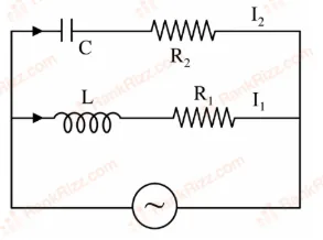
In the above circuit, C=23μF, R2=20Ω, L=103H and R1=10Ω. Current in L-R1 path is I1 and in C-R2 path it is I2. The voltage of AC source is given by, V=2002sin(100t) volts. The phase difference between I1 and I2 is:
SOLUTION
We first note that the source voltage is written as V=2002sin(100t). Comparing this with the standard form V=V0sin(ωt) we can at once read the angular frequency as ω=100rads−1.
There are two independent series branches connected across this same source.
Branch 1 (R-L branch)
The impedance of a resistor R1 in series with an inductor L is, by definition,
Z1=R1+jωL,
where the symbol j stands for −1 (conventional electrical engineering notation).
Substituting the numerical data
R1=10Ω,L=103H,ω=100rads−1,
we obtain
ωL=100×103=103Ω.
Hence
Z1=10+j103Ω.
The phase angle by which the branch current lags its voltage for an R-L circuit is given by the well-known relation
ϕ1=tan−1(R1ωL).
Substituting,
ϕ1=tan−1(10103)=tan−1(3)=60∘.
Because the term +jωL is inductive, this angle represents lag. Therefore
I1lagsVby60∘,
or equivalently, the phase of I1 is
∠I1=−60∘.
Branch 2 (R-C branch)
The impedance of a resistor R2 in series with a capacitor C is