JEE MAIN 2026 · 28 JAN S1Series LCR circuits: impedance and phaseTRANSCRIBED
The electric current in the circuit is given as . The r.m.s cm1:ent for the period t = 0 to t = T is______.
- A
- B
- C
- D
Every JEE Main question on Series LCR circuits: impedance and phase, one of the ideas inside Alternating Current: 121 questions from 2004–2026, 76 of them in the last five years. Newest first, answer key on every one. Free to read.
Questions
121
Years asked
15
Since
2004
Of the chapter
73%
Questions on Series LCR circuits: impedance and phase in each year it was asked, the latest 12 of 15.
1–20 OF 121 · NEWEST FIRST
The electric current in the circuit is given as . The r.m.s cm1:ent for the period t = 0 to t = T is______.
For the series LCR circuit connected with 220 V, 50 Hz a.c source as shown in the figure, the power factor is . The value of is______.
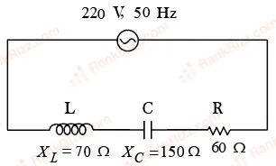
8
4
6
10
A capacitor C is first charged fully with potential difference of and disconnected from the battery. The charged capacitor is connected across an inductor having inductance L. In t s 25% of the initial energy in the capacitor is transferred to the inductor. The value of t is ____________s.
An a.c. source of angular frequency is connected across a resistor and a capacitor in series. The current is observed as . Now the frequency of the source is changed to , (keeping the voltage unchanged) the current is found to be . The ratio of resistance to reactance at frequency is
A LCR series circuit driven with V at frequency Hz has resistance , an inductance with inductive reactance and capacitance with capacitive reactance . The power factor of the circuit is _______.
0.8
0.64
0.9
0.5
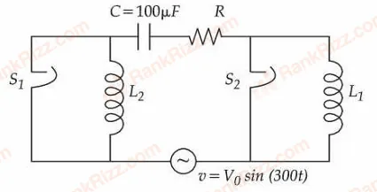
The figure given below shows an LCR series circuit with two switches and . When switch is closed keeping open, the phase difference between the current and source voltage is and phase difference is when is closed keeping open. The value of is _________ H.
An inductor stores 16 J of magnetic field energy and dissipates 32 W of thermal energy due to its resistance when an a.c. current of 2 A (rms) and frequency 5O Hz nows through it. The ratio of inductive reactance to its resistance is_____.
In a series LCR circuit with , , H, F is connected to a variable frequency a.c. source. The inductive reactance at resonant frequency is ____________ .
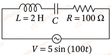
Using a variable frequency a.c. voltage source the maximum current measured in the given LCR circuit is 50 mA for V= 5 sin(100t) The values of L and R are shown in the figure. The capacitance of the capacitor (C) used is ____ µF.
An inductor of 10 mH, capacitor of 0.1 F and a resistor of 100 are connected in series across an a.c power supply 220 V, 70 Hz. The power factor of the given circuit is 0.5. The difference in the inductive reactance and capacitance reactance is . The value of is _____.
Given below are two statements : one is labelled as Assertion (A) and the other is labelled as Reason (R). Assertion (A) : Choke coil is simply a coil having a large inductance but a small resistance. Choke coils are used with fluorescent mercury-tube fittings. If household electric power is directly connected to a mercury tube, the tube will be damaged.
Reason (R): By using the choke coil, the voltage across the tube is reduced by a factor , where ω frequency of the supply across resistor R and inductor L. If the choke coil were not used, the voltage across the resistor would be the same as the applied voltage.
In the light of the above statements, choose the most appropriate answer from the options given below :
(A) is true but (R) is false
Both (A) and (R) are true and (R) is the correct explanation of (A)
(A) is false but (R) is true
Both (A) and (R) are true but (R) is not the correct explanation of (A)
An alternating current is represented by the equation ampere. The RMS value of current and the frequency of the given alternating current are
A, 100 Hz
A, 100 Hz
100 A, 50 Hz
A, 50 Hz
An ac current is represented as Amp. The r.m.s value of the current is :
50 Amp
100 Amp
10 Amp
Amp
A series LCR circuit is connected to an alternating source of emf E. The current amplitude at resonant frequency is . If the value of resistance R becomes twice of its initial value then amplitude of current at resonance will be
An electric bulb rated as 100 W-220 V is connected to an ac source of rms voltage 220 V. The peak value of current through the bulb is:
0.64 A
0.45 A
2.2 A
0.32 A
An inductor of reactance 100 , a capacitor of reactance 50 , and a resistor of resistance 50 are connected in series with an AC source of 10 V, 50 Hz. Average power dissipated by the circuit is _____ W.
In a series LCR circuit, a resistor of 300Ω, a capacitor of 25 nF and an inductor of 100 mH are used. For maximum current in the circuit, the angular frequency of the ac source is _____
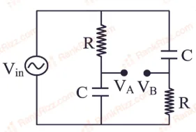
For ac circuit shown in figure, R = 100 k and C = 100 pF and the phase difference between and is . The input signal frequency is rad/sec, where 'x' is ______.
An inductor of self inductance 1 H connected in series with a resistor of ohm and an ac supply of volt, 50 Hz. Maximum current flowing in the circuit is ______ A.
RELATED ALTERNATING CURRENT TOPICS