JEE MAIN 2023 · 24 JAN S1Resonance, bandwidth and quality factorTRANSCRIBED
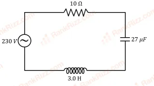
In the circuit shown in the figure, the ratio of the quality factor and the band width is _____ s.
Every JEE Main question on Resonance, bandwidth and quality factor, one of the ideas inside Alternating Current: 16 questions from 2004–2023, 7 of them in the last five years. Newest first, answer key on every one. Free to read.
Questions
16
Years asked
10
Since
2004
Of the chapter
10%
Questions on Resonance, bandwidth and quality factor in each year it was asked.
1–16 OF 16 · NEWEST FIRST
In the circuit shown in the figure, the ratio of the quality factor and the band width is _____ s.
In the circuit shown in the figure, the ratio of the quality factor and the band width is _____ s.
A series combination of resistor of resistance 100 , inductor of inductance 1 H and capacitor of capacitance 6.25 F is connected to an ac source. The quality factor of the circuit will be _____.
When you walk through a metal detector carrying a metal object in your pocket, it raises an alarm. This phenomenon works on
Electromagnetic induction
Resonance in ac circuits
Mutual induction in ac circuits
Interference of electromagnetic waves
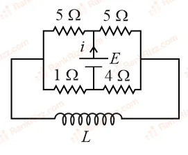
The current (i) at time and respectively for the given circuit is:
A resonance circuit having inductance H and resistance 6.28 respectively oscillates at 10 MHz frequency. The value of quality factor of this resonator is ______.
An AC circuit has , and , connected in series. The quality factor of the circuit is:
2
0.5
20
400
An ideal capacitor of capacitance 0.2 F is charged to a potential difference of 10 V. The charging battery is then disconnected. The capacitor is then connected to an ideal inductor of self inductance 0.5 mH. The current at a time when the potential difference across the capacitor is 5 V, is:
0.17 A
0.15 A
0.34 A
0.25 A
For an RLC circuit driven with voltage of amplitude and frequency , the current exhibits resonance. The quality factor, Q is given by:
In an A.C. circuit, the instantaneous e.m.f. and current are given by, , . In one cycle of A.C., the average power consumed by the circuit (in watt) and the watt-less current (in ampere) are, respectively:
50, 0
50, 10
, 10
, 0
A sinusoidal voltage V(t) = 100 sin(500t) is applied across a pure inductance of L = 0.02H. The current through the coil is:
10 cos(500t)
cos(500t)
10 sin(500t)
sin(500t)
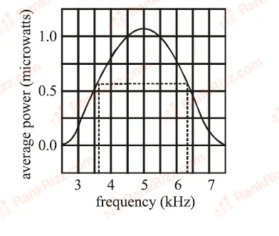
The plot given below is of the average power delivered to an LRC circuit versus frequency. The quality factor of the circuit is :
5.0
2.0
2.5
0.4
In a series L - C - R circuit, Farad, Henry and Ohm, when a constant D.C. voltage E is applied to the circuit, the capacitor acquires a charge C. The D.C. source is replaced by a sinusoidal voltage source in which the peak voltage is equal to the constant D.C. voltage E. At resonance the peak value of the charge acquired by the capacitor will be :
C
C
C
C
In a series resonant LCR circuit, the voltage across is volts and with . The resonant frequency is . At resonance the voltage across is
40 V
250 V
The self inductance of the motor of an electric fan is H. In order to impart maximum power at Hz, it should be connected to a capacitance of
In a LCR circuit capacitance is changed from to . For the resonant frequency to remain unchanged, the inductance should be changed from to
RELATED ALTERNATING CURRENT TOPICS