JEE MAIN 2020 · 03 SEP S1Capacitors in DC circuits (steady state)TRANSCRIBED
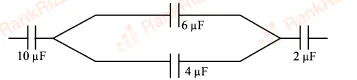
In the circuit shown in the figure, the total charge is 750 and the voltage across capacitor is 20 V. Then the charge on capacitor is:
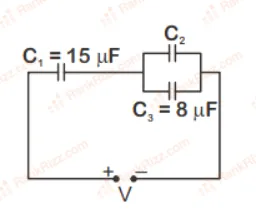
- A
- B
- C
- D
Every JEE Main question on Capacitors in DC circuits (steady state), one of the ideas inside Capacitance: 34 questions from 2012–2026, 16 of them in the last five years. Newest first, answer key on every one. Free to read.
Questions
34
Years asked
14
Since
2012
Of the chapter
20%
21–34 OF 34 · NEWEST FIRST
In the circuit shown in the figure, the total charge is 750 and the voltage across capacitor is 20 V. Then the charge on capacitor is:
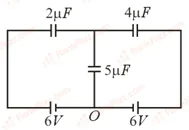
In the circuit shown, charge on the capacitor is:
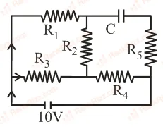
An ideal cell of emf 10V is connected in circuit shown in figure. Each resistance is . The potential difference (in V) across the capacitor when it is fully charged is ___________.
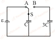
The figure shows a capacitor of capacitance C connected to a battery via a switch, having a total charge Q on it, in steady-state. When the switch S is turned from position A to position B, the energy dissipated in the circuit is
In the figure shown below, the charge on the left plate of the capacitor is . The charge on the right plate of the capacitor is:
In the given circuit, the charge on 4 μF capacitor will be:
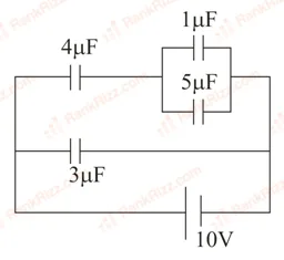
9.6 μC
5.4 μC
24 μC
13.4 μC
Determine the charge on the capacitor in the following circuit:
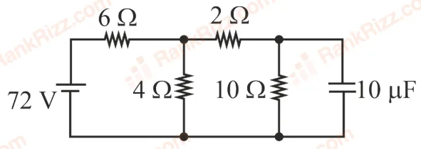
2 C
60 C
10 C
200 C
A capacitor C is charged up to a voltage V = 60 V by connecting it to battery B through switch (1). Now C is disconnected from battery and connected to a circuit consisting of two uncharged capacitors C = 3.0F and C = 6.0F through a switch (2) as shown in the figure. The sum of final charges on C and C is:
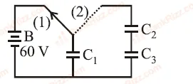
36C
20C
54C
40C
A capacitance of 2 μF is required in an electrical circuit across a potential difference of 1.0 kV. A large number of 1 μF capacitors are available which can withstand a potential difference of not more than 300 V. The minimum number of capacitors required to achieve this is:
32
2
16
24
A combination of capacitors is set up as shown in the figure. The magnitude of the electric field, due to a point charge Q (having a charge equal to the sum of the charges on the 4 F and 9 F capacitors), at a point distant 30 m from it, would equal:
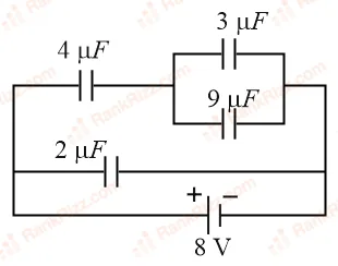
420 N/C
480 N/C
240 N/C
360 N/C
In the given circuit, charge on the 2 F capacitor changes as C is varied from 1 F to 3 F. as a function of 'C' is given properly by: (figures are drawn schematically and are not to scale)
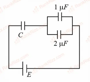
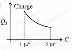
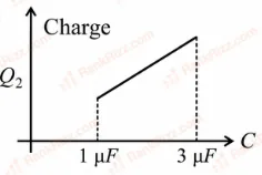
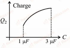
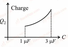
In the figure is shown a system of four capacitors connected across a 10 V battery. The charge that will flow from switch S when it is closed is:
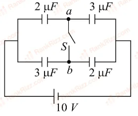
Zero
20 C from a to b
5 C from b to a
5 C from a to b
The circuit shown here has two batteries of 8.0 V and 16.0 V and three resistors 3, 9 and 9 and a capacitor of 5.0 F. How much is the current I in the circuit in steady state?
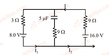
1.6 A
0.67 A
2.5 A
0.25 A
Two circuits (a) and (b) have charged capacitors of capacitance C, 2C and 3C with open switches. Charges on each of the capacitor are as shown in the figures. On closing the switches
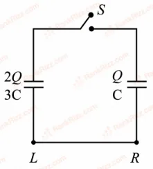
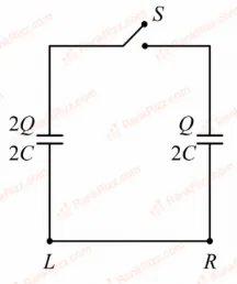
Circuit (a) Circuit (b)
No charge flows in (a) but charge flows from to in (b)
Charges flow from to in both (a) and (b)
Charges flow from to in (a) and from to in (b)
No charge flows in (a) but charge flows from to in (b)
RELATED CAPACITANCE TOPICS