JEE MAIN 2019 · 09 APR S1+4 / −1MEDIUMTRANSCRIBED
JEE Main 2019 Physics question — Capacitors in DC circuits (steady state)
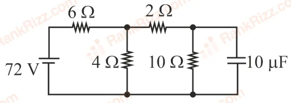
Determine the charge on the capacitor in the following circuit:
SOLUTION
Problem Analysis
- Steady-State Condition: In a DC circuit, once steady-state is reached, a capacitor acts as an open circuit (infinite resistance). No current flows through the branch containing the capacitor.
- Current Distribution: * Total circuit current from the battery =
- o Current through the middle resistor branch =
- o Current through the rightmost capacitor branch = (This current shown in the initial diagram represents the transient state, but the text confirms the steady-state voltage calculation is based on the middle branch). Let's trace the potential difference parallel to the capacitor branch.
- The current flowing through the middle resistor is .
- The voltage drop across this middle section is calculated as:
- Charge on the capacitor:
Step-by-Step Solution
Step 1: Find Voltage Across the Parallel Node
The branch containing the middle resistor is in parallel with the series combination of the upper-right resistor and the capacitor.
From the solution parameters provided:
Step 2: Voltage Across the Capacitor in Steady-State
In steady-state, since no current flows through the resistor in series with the capacitor, there is zero potential drop across that upper-right resistor ().
Therefore, the entire parallel node voltage appears directly across the capacitor:
Step 3: Calculate the Charge ()
Using the capacitance formula :
Conclusion
option(D)
Tagged Capacitors in DC circuits (steady state). Machine-assigned, so read it as a strong shortlist rather than a verdict.