JEE MAIN 2026 · 04 APR S2Series and parallel combinations of capacitorsTRANSCRIBED
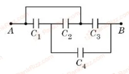
From the circuit given below, the capacitance between terminals A and B shown in the circuit is ______ F.
(take F and F.)
- A
F
- B
F
- C
F
- D
F
Every JEE Main question on Series and parallel combinations of capacitors, one of the ideas inside Capacitance: 29 questions from 2005–2026, 15 of them in the last five years. Newest first, answer key on every one. Free to read.
Questions
29
Years asked
13
Since
2005
Of the chapter
17%
Questions on Series and parallel combinations of capacitors in each year it was asked, the latest 12 of 13.
1–20 OF 29 · NEWEST FIRST
From the circuit given below, the capacitance between terminals A and B shown in the circuit is ______ F.
(take F and F.)
F
F
F
F
A capacitor P with capacitance is fully charged with a potential difference of 6.0 V and disconnected from the battery. The charged capacitor P is connected across another capacitor Q with capacitance . The charge on capacitor Q when equilibrium is established will be (assume capacitor Q does not have any charge initially), the value of is _________.
Using a battery, a 100 pF capacitor is charged to 60 V and then the battery is removed. After that, a second uncharged capacitor is connected to the first capacitor in parallel. If the final voltage across the second capacitor is 20 V, its capacitance is (in pF):
600
200
400
100
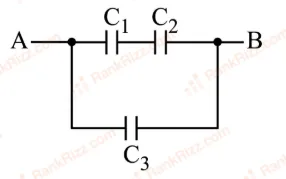
Three parallel plate capacitors , and each of capacitance 5 F are connected as shown in figure. The effective capacitance between points A and B, when the space between the parallel plates of capacitor is filled with a dielectric medium having dielectric constant of 4, is :
22.5 F
7.5 F
9 F
30 F
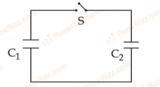
A capacitor , is charged to a potential difference of using a battery. The battery is removed and another capacitor, is inserted in place of the battery. When the switch 'S' is closed, the charge flows between the capacitors for some time until equilibrium condition is reached. What are the charges ( and on the capacitors and when equilibrium condition is reached.
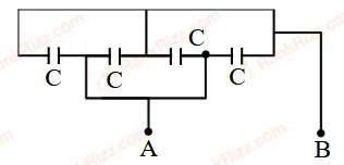
Four capacitors each of capacitance are connected as shown in the figure. The capacitance between points A and B is ________ .
A galvanometer G of resistance is connected in the given circuit. The ratio of charge stored in and is
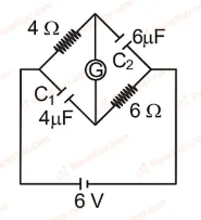
1
Three capacitors of capacitances and are connected in parallel to a supply of . Energy stored in the above combination is . When these capacitors are connected in series to the same supply, the stored energy is . The value of is ______.
A capacitor of capacitance and potential has energy . It is connected to another capacitor of capacitance and potential . Then the loss of energy is , where is ______.
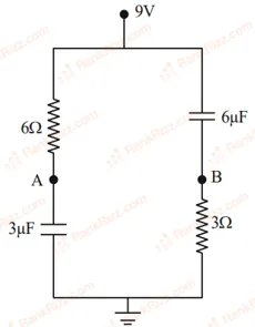
In the given figure, the charge stored in F capacitor, when points and are joined by a connecting wire is ______ C.
The equivalent capacitance of the combination shown is
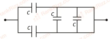
2 C
C
4 C
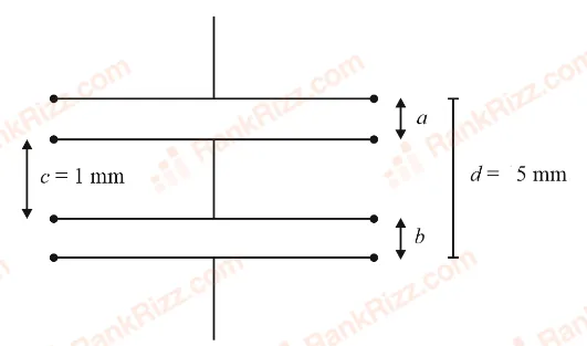
As shown in the figure, two parallel plate capacitors having equal plate area of 200 cm are joined in such a way that . The equivalent capacitance of the combination is . The value of is ______.
The total charge on the system of capacitance , , and connected in parallel is (Assume a battery of is connected to the combination)
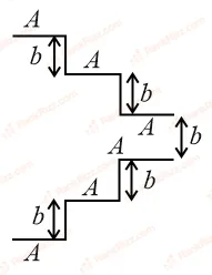
A parallel plate capacitor is made up of stair like structure with a plate area of each stair and that is connected with a wire of length , as shown in the figure. The capacitance of the arrangement is . The value of is ______.
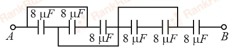
The equivalent capacitance between points and in below shown figure will be ______ F.
Two equal capacitors are first connected in series and then in parallel. The ratio of the equivalent capacities in the two cases will be:
1 : 2
1 : 4
4 : 1
2 : 1
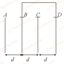
Four identical rectangular plates with length, cm and breadth, cm are arranged as shown in figure. The equivalent capacitance between and is . The value of is ________. (Round off to the Nearest Integer)
Effective capacitance of parallel combination of two capacitors and is 10F. When these capacitors are individually connected to a voltage source of 1V, the energy stored in the capacitor is 4 times that of . If these capacitors are connected in series, their effective capacitance will be:
4.2 F
3.2 F
1.6 F
8.4 F
Two capacitors of capacitances and are charged to potential differences and , respectively. These are then connected in parallel in such a manner that the positive terminal of one is connected to the negative terminal of the other. The final energy of this configuration is:
zero
A 60 pF capacitor is fully charged by a 20 V supply. It is then disconnected from the supply and is connected to another uncharged 60 pF capacitor in parallel. The electrostatic energy that is lost in this process by the time the charge is redistributed between them is (in nJ)
RELATED CAPACITANCE TOPICS