RankRizz

Motional emf in moving rods and loops — JEE Main Previous Year Questions

Every JEE Main question on Motional emf in moving rods and loops, one of the ideas inside Electromagnetic Induction: 55 questions from 2005–2026, 32 of them in the last five years. Newest first, answer key on every one. Free to read.

Questions

55

Years asked

16

Since

2005

Of the chapter

31%

Every Motional emf in moving rods and loops question

41–55 OF 55 · NEWEST FIRST

JEE MAIN 2021 · 25 JUL S1Motional emf in moving rods and loopsTRANSCRIBED

A circular conducting coil of radius 1 m is being heated by the change of magnetic field B⃗\vec{B} passing perpendicular to the plane in which the coil is laid. The resistance of the coil is 2 μΩ\mu\Omega. The magnetic field is slowly switched off such that its magnitude changes in time as
B=4π×10−3T(1−t100)B = \frac{4}{\pi} \times 10^{-3} T\left(1 - \frac{t}{100}\right)
The energy dissipated by the coil before the magnetic field is switched off completely is E=E = ___ mJ.

JEE MAIN 2020 · 05 SEP S2Motional emf in moving rods and loopsTRANSCRIBED

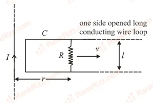
An infinitely long straight wire carrying current I, one side opened rectangular loop and a conductor C with a sliding connector are located in the same plane, as shown in the figure. The connector has length ll and resistance RR. It slides to the right with a velocity vv. The resistance of the conductor and the self inductance of the loop are negligible. The induced current in the loop, as a function of separation rr, between the connector and the straight wire is:

Figure for JEE Main 2020 Physics question on Motional emf in moving rods and loops
  1. A

    μ04πIvlRr\frac{\mu_0}{4\pi}\frac{Ivl}{Rr}

  2. B

    μ0πIvlRr\frac{\mu_0}{\pi}\frac{Ivl}{Rr}

  3. C

    2μ0πIvlRr\frac{2\mu_0}{\pi}\frac{Ivl}{Rr}

  4. D

    μ02πIvlRr\frac{\mu_0}{2\pi}\frac{Ivl}{Rr}

JEE MAIN 2019 · 08 APR S1Motional emf in moving rods and loopsTRANSCRIBED

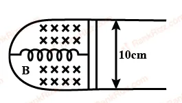
A thin strip 10 cm long is on a U shaped wire of negligible resistance and it is connected to a spring of spring constant 0.5 N m−1^{-1} (see figure). The assembly is kept in a uniform magnetic field of 0.1 T. If the strip is pulled from its equilibrium position and released, the number of oscillations it performs before its amplitude decreases by a factor of e is N. If the mass of the strip is 50 grams, its resistance 10Ω\Omega and air drag negligible, N will be close to:

Figure for JEE Main 2019 Physics question on Motional emf in moving rods and loops
  1. A

    1000

  2. B

    5000

  3. C

    10000

  4. D

    50000

JEE MAIN 2019 · 12 JAN S2Motional emf in moving rods and loopsTRANSCRIBED

A 10 m long horizontal wire extends from North East to South West. It is falling with a speed of 5.0 m s−1^{-1}, at right angles to the horizontal component of the earth's magnetic field of 0.3×10−40.3 \times 10^{-4} Wb m−2^{-2}. The value of the induced emf in the wire is:

  1. A

    0.3×10−30.3 \times 10^{-3} V

  2. B

    1.1×10−31.1 \times 10^{-3} V

  3. C

    2.5×10−32.5 \times 10^{-3} V

  4. D

    1.5×10−31.5 \times 10^{-3} V

JEE MAIN 2019 · 10 JAN S1Motional emf in moving rods and loopsTRANSCRIBED

A solid metal cube of edge length 2 cm is moving in the positive y-direction, at a constant speed of 6 m s−1^{-1}. There is a uniform magnetic field of 0.1 T in the positive z-direction. The potential difference between the two faces of the cube, perpendicular to the x-axis, is:

  1. A

    12 mV

  2. B

    1 mV

  3. C

    2 mV

  4. D

    6 mV

JEE MAIN 2019 · 12 APR S1Motional emf in moving rods and loopsTRANSCRIBED

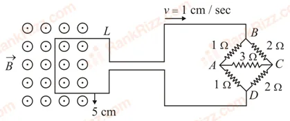
The figure shows a square loop L of side 5 cm which is connected to a network of resistances. The whole setup is moving towards the right with a constant speed of 1 cm s−1^{-1}. At some instant, a part of L is in a uniform magnetic field of 1T perpendicular to the plane of the loop. If the resistance of L is 1.7 Ω, the current in the loop at that instant will be close to:

Figure for JEE Main 2019 Physics question on Motional emf in moving rods and loops
  1. A

    115 μA

  2. B

    60 μA

  3. C

    150 μA

  4. D

    170 μA

JEE MAIN 2018 · 15 APR S2Motional emf in moving rods and loopsTRANSCRIBED

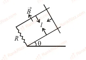
A copper rod of mass m slides under gravity on two smooth parallel rails, with separation l and set at an angle of θ\theta with the horizontal. At the bottom, rails are joined by a resistance R. There is a uniform magnetic field B normal to the plane of the rails, as shown in the figure. The terminal speed of the copper rod is:

Figure for JEE Main 2018 Physics question on Motional emf in moving rods and loops
  1. A

    mgRcos⁡θB2l2\frac{mgR\cos\theta}{B^2 l^2}

  2. B

    mgRsin⁡θB2l2\frac{mgR\sin\theta}{B^2 l^2}

  3. C

    mgRtan⁡θB2l2\frac{mgR\tan\theta}{B^2 l^2}

  4. D

    mgRcot⁡θB2l2\frac{mgR\cot\theta}{B^2 l^2}

JEE MAIN 2016 · 10 APR ONLINEMotional emf in moving rods and loopsTRANSCRIBED

A fighter plane of length 20 m, wing span (distance from tip of one wing to the tip of the other wing) of 15 m and height 5 m is flying towards east over Delhi. Its speed is 240 m s−1^{-1}. The earth's magnetic field over Delhi is 5×10−55 \times 10^{-5} T with the declination angle ~0° and dip of θ\theta such that sin⁡θ=23\sin \theta = \frac{2}{3}. If the voltage developed is VBV_B between the lower and upper side of the plane and VWV_W between the tips of the wings then VBV_B and VWV_W are close to:

  1. A

    VB=40V_B = 40 mV; VW=135V_W = 135 mV with left side of pilot at higher voltage

  2. B

    VB=45V_B = 45 mV; VW=120V_W = 120 mV with right side of pilot at higher voltage

  3. C

    VB=40V_B = 40 mV; VW=135V_W = 135 mV with right side of pilot at higher voltage

  4. D

    VB=45V_B = 45 mV; VW=120V_W = 120 mV with left side of pilot at higher voltage

JEE MAIN 2016 · 10 APR ONLINEMotional emf in moving rods and loopsTRANSCRIBED

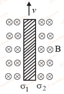
Consider a thin metallic sheet perpendicular to the plane of the paper moving with speed v in a uniform magnetic field B going into the plane of the paper (see the figure below). If the charge densities σ1\sigma_1 and σ2\sigma_2 are induced on the left and right surfaces respectively of the sheet, then (ignore fringe effects)

Figure for JEE Main 2016 Physics question on Motional emf in moving rods and loops
  1. A

    σ1=−ϵ0vB2\sigma_1 = \frac{-\epsilon_0 vB}{2}, σ2=ϵ0vB2\sigma_2 = \frac{\epsilon_0 vB}{2}

  2. B

    σ1=ϵ0vB\sigma_1 = \epsilon_0 vB, σ2=−ϵ0vB\sigma_2 = -\epsilon_0 vB

  3. C

    σ1=ϵ0vB2\sigma_1 = \frac{\epsilon_0 vB}{2}, σ2=−ϵ0vB2\sigma_2 = \frac{-\epsilon_0 vB}{2}

  4. D

    σ1=σ2=ϵ0vB\sigma_1 = \sigma_2 = \epsilon_0 vB

JEE MAIN 2014 · 19 APR ONLINEMotional emf in moving rods and loopsTRANSCRIBED

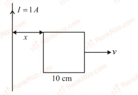
A square frame of side 10 cm and a long straight wire carrying current 1 A are in the plane of the paper. Starting from close to the wire, the frame moves towards the right with a constant speed of 10 m s−1^{-1} (see figure). The e.m.f induced at the time the left arm of the frame is at x = 10 cm from the wire is:

Figure for JEE Main 2014 Physics question on Motional emf in moving rods and loops
  1. A

    0.75 μ\muV

  2. B

    1 μ\muV

  3. C

    2 μ\muV

  4. D

    0.5 μ\muV

JEE MAIN 2013 · 07 APR ONLINEMotional emf in moving rods and loopsTRANSCRIBED

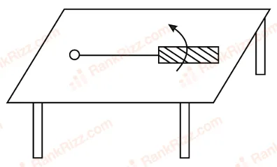
A metallic rod of length ll is tied to a string of length 2l2l and made to rotate with angular speed ω\omega on a horizontal table with one end of the string fixed. If there is a vertical magnetic field B in the region, the e.m.f. induced across the ends of the rod is:

Figure for JEE Main 2013 Physics question on Motional emf in moving rods and loops
  1. A

    4Bωl22\frac{4B\omega l^2}{2}

  2. B

    5Bωl22\frac{5B\omega l^2}{2}

  3. C

    2Bωl22\frac{2B\omega l^2}{2}

  4. D

    3Bωl22\frac{3B\omega l^2}{2}

JEE MAIN 2012Motional emf in moving rods and loopsTRANSCRIBED

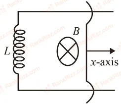
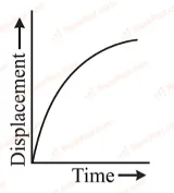
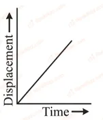
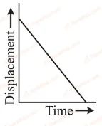
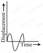
A coil of self inductance LL is connected at one end of two rails as shown in figure. A connector of length ll, mass mm can slide freely over the two parallel rails. The entire set up is placed in a magnetic field of induction BB going into the page. At an instant t=0t=0 an initial velocity v0v_0 is imparted to it and as a result of that it starts moving along xx-axis. The displacement of the connector is represented by the figure.

Figure for JEE Main 2012 Physics question on Motional emf in moving rods and loops
  1. A
    Figure for JEE Main 2012 Physics question on Motional emf in moving rods and loops
  2. B
    Figure for JEE Main 2012 Physics question on Motional emf in moving rods and loops
  3. C
    Figure for JEE Main 2012 Physics question on Motional emf in moving rods and loops
  4. D
    Figure for JEE Main 2012 Physics question on Motional emf in moving rods and loops
JEE MAIN 2011Motional emf in moving rods and loopsTRANSCRIBED

A boat is moving due east in a region where the earth's magnetic field is 5.0×10⁻⁵ NA−1m−15.0 \times 10^{-5} \, \text{NA}^{-1} \text{m}^{-1} due north and horizontal. The boat carries a vertical aerial 2 m2 \, \text{m} long. If the speed of the boat is 1.50 ms−11.50 \, \text{ms}^{-1}, the magnitude of the induced emf in the wire of aerial is:

  1. A

    0.75 mV0.75 \, \text{mV}

  2. B

    0.50 mV0.50 \, \text{mV}

  3. C

    0.15 mV0.15 \, \text{mV}

  4. D

    1 mV1 \, \text{mV}

JEE MAIN 2010Motional emf in moving rods and loopsTRANSCRIBED

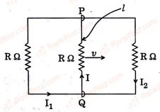
A rectangular loop has a sliding connector PQ of length ℓ\ell and resistance RΩR\Omega and it is moving with a speed vv as shown. The set-up is placed in a uniform magnetic field going into the plane of the paper. The three currents I1,I2I_1, I_2 and II are
Figure for JEE Main 2010 Physics question on Motional emf in moving rods and loops

  1. A

    I1=−I2=BℓvR,I=2BℓvRI_1 = -I_2 = \frac{B\ell v}{R}, I = \frac{2 B\ell v}{R}

  2. B

    I1=I2=Bℓv3R,I=2Bℓv3RI_1 = I_2 = \frac{B\ell v}{3R}, I = \frac{2 B\ell v}{3R}

  3. C

    I1=I2=I=BℓvRI_1 = I_2 = I = \frac{B\ell v}{R}

  4. D

    I1=I2=Bℓv6R,I=Bℓv3RI_1 = I_2 = \frac{B\ell v}{6R}, I = \frac{B\ell v}{3R}

JEE MAIN 2005Motional emf in moving rods and loopsTRANSCRIBED

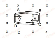
One conducting U tube can slide inside another as shown in figure, maintaining electrical contacts between the tubes. The magnetic field BB is perpendicular to the plane of the figure. If each tube moves towards the other at a constant speed VV, then the emf induced in the circuit in terms of BB, ℓ\ell and VV where ℓ\ell is the width of each tube will be Figure for JEE Main 2005 Physics question on Motional emf in moving rods and loops

  1. A

    BℓVB \ell V

  2. B

    −BℓV-B \ell V

  3. C

    zero

  4. D

    2BℓV2 B \ell V