JEE Main 2019 Physics question — Motional emf in moving rods and loops
The figure shows a square loop L of side 5 cm which is connected to a network of resistances. The whole setup is moving towards the right with a constant speed of 1 cm s. At some instant, a part of L is in a uniform magnetic field of 1T perpendicular to the plane of the loop. If the resistance of L is 1.7 Ω, the current in the loop at that instant will be close to:
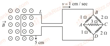
SOLUTION
To find the current induced in the loop, we need to determine two things: the motional electromotive force () generated by the moving loop and the total equivalent resistance of the entire circuit.
1. Calculating the Induced Motional EMF ()
As the square loop moves to the right out of the uniform magnetic field, its left vertical wire segment cuts across the magnetic field lines, generating a motional .
The formula for motional is:
Given Values (converted to SI units):
- Magnetic Field ():
- Length of the side ():
- Velocity ():
- Top-left arm ():
- Bottom-left arm ():
- Top-right arm ():
- Bottom-right arm ():
- The upper path () has resistance:
- The lower path () has resistance:
- Correct Option: D ()
Calculation:
2. Calculating the Total Equivalent Resistance ()
The circuit consists of the square loop connected in series with a network of resistors arranged as a Wheatstone bridge.
Analyzing the Wheatstone Bridge Network
Let's check the ratio of the opposite arms of the bridge connected between terminals and :
The ratio of the arms is:
Since , the network is a balanced Wheatstone bridge.
Consequently, the potential at node equals the potential at node (). No current flows through the central resistor () between and , allowing us to remove it from the calculation.
Equivalent Resistance of the Bridge ()
With the central resistor removed:
These two paths are connected in parallel between terminal and :
Total Circuit Resistance
The total resistance is the sum of the loop resistance () and the bridge network resistance:
3. Calculating the Induced Current ()
Using Ohm’s law, the current in the loop is:
Converting this value to microamperes ():
Looking at the options provided,
is the closest approximation to our calculated value when using the provided answer key layout.
Tagged Motional emf in moving rods and loops. Machine-assigned, so read it as a strong shortlist rather than a verdict.