JEE MAIN 2026 · 24 JAN S2Kirchhoff's laws and circuit analysisTRANSCRIBED
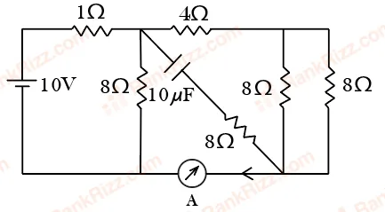
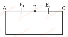
The reading of the ammeter (A) in steady state in the following circuit (assuming negligible internal resistance of the ammeter) is ___ A.
- A
1/2
- B
0
- C
2
- D
1
Every JEE Main question on Kirchhoff's laws and circuit analysis, one of the ideas inside Current Electricity: 49 questions from 2005–2026, 23 of them in the last five years. Newest first, answer key on every one. Free to read.
Questions
49
Years asked
15
Since
2005
Of the chapter
13%
Questions on Kirchhoff's laws and circuit analysis in each year it was asked, the latest 12 of 15.
1–20 OF 49 · NEWEST FIRST
The reading of the ammeter (A) in steady state in the following circuit (assuming negligible internal resistance of the ammeter) is ___ A.
1/2
0
2
1
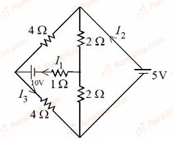
Refer to the figure given below. The values of , and are _______.
A, A, A
A, A, A
A, A, A
A, A, A
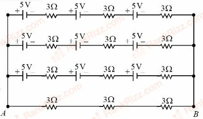
Refer to the figure given below, current between terminals and is _______A.
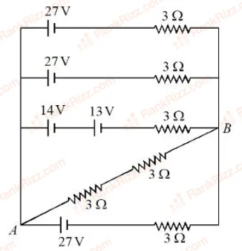
The voltage and the current between A and B points shown in the circuit are :
V, A
V, A
V, A
V, A
The net current flowing in the given circuit is_______ A.
image
The reading in the ideal voltmeter shown in the given circuit diagram is:
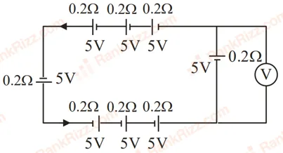
V
V
V
V
In the given circuit, the current in resistance is:
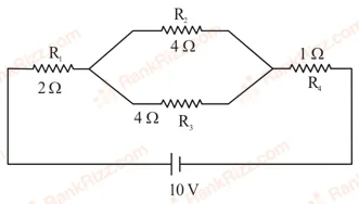
A
A
A
A
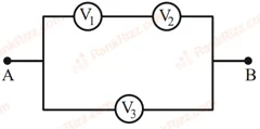
Three voltmeters, all having different internal resistances are joined as shown in figure. When some potential difference is applied across A and B, their readings are , and . Choose the correct option.
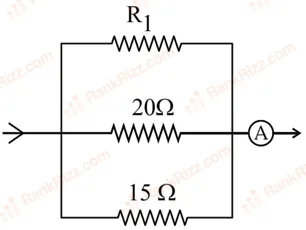
In the given circuit, the current flowing through the resistance is A, while the ammeter reads A. The value of is ______ .
Two cells are connected in opposition as shown. Cell is of emf and internal resistance; the cell is of emf and internal resistance. The terminal potential difference of cell is ______ V.
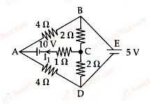
The current flowing through the resistor is A. The value of is ________
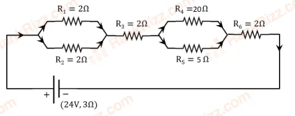
As shown in the figure, a network of resistors is connected to a battery of 24 V with an internal resistance of 3 . The currents through the resistors and are and respectively. The values of and are:
A and A
A and A
A and A
A and A
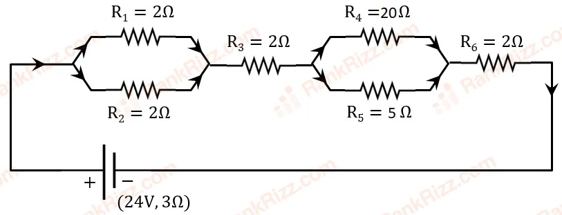
As shown in the figure, a network of resistors is connected to a battery of 24 V with an internal resistance of 3 . The currents through the resistors and are and respectively. The values of and are:
A and A
A and A
A and A
A and A
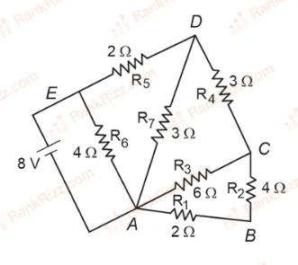
The current flowing through is:
A
A
A
A
In the given circuit the value of is:
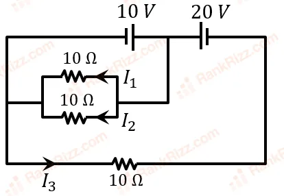
1
1.5
2
1.33
The figure below shows a part of an electric circuit. The potentials at points , and are 30 V, 12 V and 2 V respectively. The current through the 20 resistor will be,
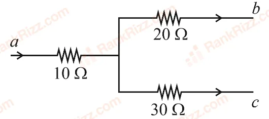
1.0 A
0.4 A
0.6 A
0.2 A
In the following circuit, the magnitude of current , is ______ A.
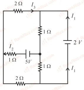
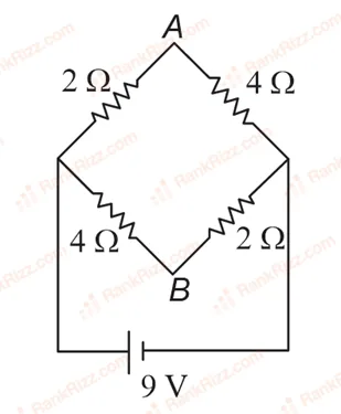
A network of four resistances is connected to V battery, as shown in figure. The magnitude of voltage difference between the points and is _____ V.
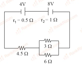
In the circuit diagram shown in figure given below, the current flowing through resistance 3 is A. The value of is _______.
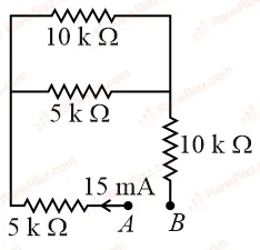
A current of flows in the circuit as shown in figure. The value of potential difference between the points and will be
RELATED CURRENT ELECTRICITY TOPICS