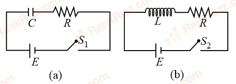
In the given circuits (a) and (b), switches and are closed at and kept close for a long time. The variation of currents in the two circuits for are shown in the options. (Figures are schematic and not drawn to scale.)
- A
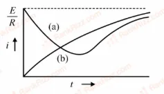
- B
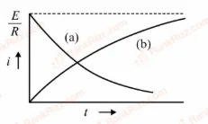
- C
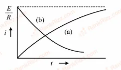
- D
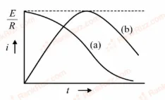
Every JEE Main question on LR circuits: growth and decay of current, one of the ideas inside Electromagnetic Induction: 29 questions from 2005–2026, 9 of them in the last five years. Newest first, answer key on every one. Free to read.
Questions
29
Years asked
15
Since
2005
Of the chapter
16%
21–29 OF 29 · NEWEST FIRST
In the given circuits (a) and (b), switches and are closed at and kept close for a long time. The variation of currents in the two circuits for are shown in the options. (Figures are schematic and not drawn to scale.)


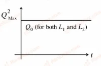
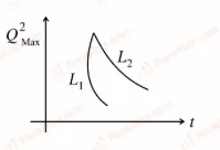
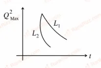
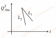
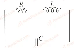
An LCR circuit is equivalent to a damped pendulum. In an LCR circuit the capacitor is charged to and then connected to the L and R as shown below:
If a student plots graphs of the square of maximum charge on the capacitor with time (t) for two different values and () of L then which of the following represents this graph correctly? (plots are schematic and not drawn to scale)


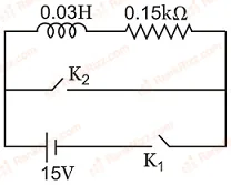
An inductor H and a resistor k are connected in series to a battery of 15 V E.M.F. in the circuit shown below. The key has been kept closed for a long time. Then at , is opened and key is closed simultaneously. At ms, the current in the circuit will be: (Take, )

0.67 mA
100 mA
67 mA
6.7 mA
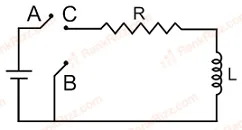
In the circuit shown here, the point 'C' is kept connected to point 'A' till the current flowing through the circuit becomes constant. Afterward, suddenly, point 'C' is disconnected from point 'A' and connected to point 'B' at time . Ratio of the voltage across resistance and the inductor at will be equal to:

1
-1
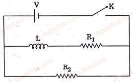
In the circuit shown below, the key K is closed at . The current through the battery is

at and at
at and at
at and at
at and at
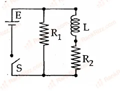
An inductor of inductance mH and resistors of resistances and are connected to a battery of emf V as shown in the figure. The internal resistance of the battery is negligible. The switch is
closed at . The potential drop across as a function of time is
V
V
V
V
An ideal coil of is connected in series with a resistance of and a battery of . 2 second after the connection is made the current flowing in amperes in the circuit is
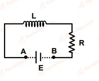
An inductor , a resistor and a battery are initially connected in series as shown in the figure. After a long time the battery is disconnected after short circuiting the points and .
What is the current in the circuit after ?
1 A
0.1 A
A coil of inductance mH and resistance is connected to a source of voltage V. The current reaches half of its steady state value in
s
s
s
s