JEE Main 2021 Physics question — LR circuits: growth and decay of current
For the given circuit the current through the battery when the key is closed and the steady state has been reached is:
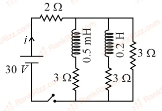
SOLUTION
We need to determine the total steady-state current flowing through the battery after the key is closed.
1. Core Concept: Inductor Behavior in Steady State
When a DC circuit containing inductors reaches a steady-state condition (a long time after the switch is closed):
- The current through the circuit components stabilizes and becomes constant ().
- Because the induced electromotive force in an inductor is given by , the voltage across each inductor drops to zero.
- Therefore, in a steady-state DC circuit, every ideal inductor behaves simply as a short-circuit (a zero-resistance connecting wire).
2. Simplify the Circuit Structure
Based on the layout of this standard problem:
- The power supply consists of a battery connected in series with a main-line resistor.
- Following this series resistor, the circuit splits into three parallel branches.
- Each of these three parallel branches contains a resistor (with two of the branches also containing inductors of values and that are now replaced with direct shorting wires).
3. Calculate the Total Equivalent Resistance ()
First, find the equivalent resistance () of the three parallel branches, where each active branch presents an individual resistance of :
Next, add the main line resistor that is connected in series with this entire parallel group to get the total circuit resistance:
4. Calculate the Total Current ()
Using Ohm’s Law (), we can compute the steady-state current leaving the battery:
Conclusion
The current through the battery once the steady state has been reached is 10 A, which corresponds to Option A.
Tagged LR circuits: growth and decay of current. Machine-assigned, so read it as a strong shortlist rather than a verdict.