JEE Main 2022 Physics question — p-n junction diode and its characteristics
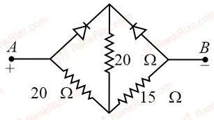
Two ideal diodes are connected in the network as shown in figure. The equivalent resistance between and is ______ .
SOLUTION
We need to find the equivalent resistance between terminals and for the given diode-resistor network.
1. Analyze the Diode Conditions
From the schematic shown , terminal is connected to the positive terminal () of the voltage source, and terminal is connected to the negative terminal ().
Let's determine the bias state of each ideal diode based on the conventional current flowing from to :
- Left Diode: The current entering from terminal encounters the p-side (anode) of the left diode. This makes it forward-biased, meaning it acts as a short circuit (closed switch or simple connecting wire).
- Right Diode: The current attempting to reach terminal encounters the n-side (cathode) of the right diode. This makes it reverse-biased, meaning it acts as an open circuit (broken wire or infinite resistance), and no current can pass through this upper-right branch.
2. Simplify the Circuit
By substituting the forward-biased diode with a short circuit and removing the reverse-biased branch completely, the network simplifies significantly:
- The top junction is now directly tied to the left junction (terminal ) via the shorted left diode.
- This places the upper central vertical resistor directly in parallel with the lower-left diagonal resistor.
Let's calculate the equivalent resistance () of these two parallel resistors:
3. Calculate the Total Equivalent Resistance ()
This parallel combination () is in series with the remaining lower-right diagonal resistor leading straight to terminal :
Conclusion
The equivalent resistance between and is 25 .
Tagged p-n junction diode and its characteristics. Machine-assigned, so read it as a strong shortlist rather than a verdict.