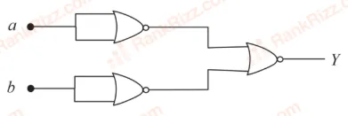
The logic performed by the circuit shown in figure is equivalent to
AND
NOR
OR
NAND
Outputs of the first two NOR gates with tied inputs: Ya=a+a‾=aˉ,Yb=b+b‾=bˉ\text{Outputs of the first two NOR gates with tied inputs: } Y_a = \overline{a + a} = \bar{a}, \quad Y_b = \overline{b + b} = \bar{b}Outputs of the first two NOR gates with tied inputs: Ya=a+a=aˉ,Yb=b+b=bˉ
Output of the final NOR gate: Y=Ya+Yb‾=aˉ+bˉ‾\text{Output of the final NOR gate: } Y = \overline{Y_a + Y_b} = \overline{\bar{a} + \bar{b}}Output of the final NOR gate: Y=Ya+Yb=aˉ+bˉ
Applying De Morgan’s Law: Y=aˉ‾⋅bˉ‾=a⋅b ⟹ AND gate\text{Applying De Morgan's Law: } Y = \overline{\bar{a}} \cdot \overline{\bar{b}} = a \cdot b \implies \text{AND gate}Applying De Morgan’s Law: Y=aˉ⋅bˉ=a⋅b⟹AND gate
Tagged Logic gates and digital circuits. Machine-assigned, so read it as a strong shortlist rather than a verdict.