JEE MAIN 2024 · 04 APR S1+4 / −1EASYTRANSCRIBED
JEE Main 2024 Physics question — Diode circuits and rectifiers
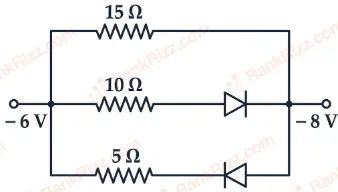
The value of net resistance of the network as shown in the given figure is:
SOLUTION
First, note the potentials:
left node = −6 V, right node = −8 V
So left is at higher potential current tends to flow left right.
Now check diodes:
• middle branch (10 Ω): diode allows left right forward biased
• bottom branch (5 Ω): diode allows right left reverse biased (no current)
So active branches:
• top: 15 Ω
• middle: 10 Ω
(bottom 5 Ω is inactive)
Now these two are in parallel:
Tagged Diode circuits and rectifiers. Machine-assigned, so read it as a strong shortlist rather than a verdict.