JEE Main 2021 Physics question — Capacitors in DC circuits (steady state)
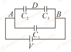
Three capacitors F, F and F are connected as shown in the figure. Find the ratio of the charges on capacitors , and respectively.
SOLUTION
We need to find the ratio of the charges on the capacitors , , and arranged in the given circuit configuration.
1. Analyze the Circuit Diagram Connections
Let's look closely at the nodes and connections across the network :
- Let the potential at terminal be and the potential at terminal be . The total potential difference supplied by the battery source is .
- Capacitor : One plate is connected directly to node and the other plate is connected directly to node . Therefore, is in a standalone parallel branch connected directly across the full potential difference .
- Capacitors and : They are connected in series with each other along the top branch. The left plate of connects to node , their shared junction forms a common node , and the right plate of connects to node . Therefore, this entire combined series branch ( and ) is in parallel with across the potential difference .
2. Calculate the Charges on Each Capacitor
The values of the three capacitors are given as:
Charge on ():
Since the voltage across is the full voltage :
Charges on and ( and ):
Because and are connected together in series within their branch, the same amount of electric charge flows through both of them (). This shared charge is determined by the equivalent capacitance () of that branch multiplied by the potential difference :
Now, calculate the charge on this series branch:
3. Determine the Ratio of the Charges
We can now construct the required ratio of the charges on , , and respectively:
Dividing throughout by the common factor gives:
Final Answer: 1 : 2 : 2 (Option D)
Tagged Capacitors in DC circuits (steady state). Machine-assigned, so read it as a strong shortlist rather than a verdict.