JEE Main 2021 Physics question — Series LCR circuits: impedance and phase
In the given circuit the AC source has rad s. Considering the inductor and capacitor to be ideal, what will be the current flowing through the circuit?
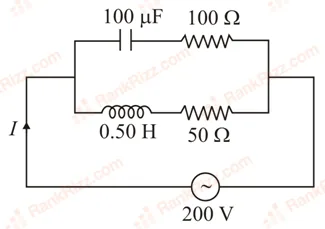
SOLUTION
We need to determine the total rms current flowing through the given parallel alternating current (AC) circuit arrangement.
1. Identify the Given Parameters
From the problem, the parallel circuit consists of two parallel branches connected across an AC voltage source of with an angular frequency of :
- Branch 1 (Top RC series path): Resistance and Capacitance .
- Branch 2 (Bottom RL series path): Resistance and Inductance .
2. Calculate Reactances and Branch Impedances
We first calculate the capacitive reactance () and inductive reactance (), followed by the total impedance of each path:
-
Capacitive Branch (Branch 1):
The reactance of the ideal capacitor is:The impedance () of the series RC branch is:
-
Inductive Branch (Branch 2):
The reactance of the ideal inductor is:The impedance () of the series RL branch is:
3. Determine Individual Branch Currents and Phase Angles
The voltage drop across both parallel branches is equal to the source voltage ():
-
Current in Branch 1 ():
Since it is an RC circuit, the current leads the voltage by a phase angle of .
-
Current in Branch 2 ():
Since it is an RL circuit, the current lags behind the voltage by a phase angle of .
4. Calculate total Phasor Current ()
The net phase difference between the leading branch current () and lagging branch current () is . Because the two current vectors are perpendicular (in quadrature), their phasor sum can be evaluated using the Pythagorean theorem:
Conclusion
The total current flowing through the AC circuit configuration is 3.16 A.
Tagged Series LCR circuits: impedance and phase. Machine-assigned, so read it as a strong shortlist rather than a verdict.