JEE Main 2021 Physics question — Series LCR circuits: impedance and phase
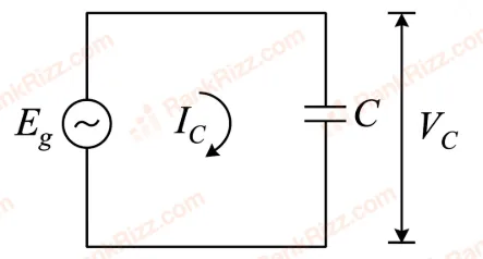
In a circuit consisting of a capacitance and a generator with alternating emf, , and are the voltage and current. Correct phasor diagram for such circuit is:
SOLUTION
In a purely capacitive circuit with , the current leads the voltage by . This is because in a capacitor, charge builds up as voltage rises, and maximum current flows when the voltage is zero (rate of change is maximum), while zero current flows when the voltage is at its peak.
Specifically, the current is:
while the voltage across the capacitor is (in phase with the applied emf).
In the phasor diagram, (or the emf ) is taken as the reference phasor, and leads by (i.e., is drawn ahead of in the direction of rotation). The correct phasor diagram shows perpendicular to and leading , which corresponds to phasor diagram (3).
Tagged Series LCR circuits: impedance and phase. Machine-assigned, so read it as a strong shortlist rather than a verdict.